Pivotal driving tool assembly

a technology of driving tool and assembly, which is applied in the direction of screwdrivers, wrenches, rotary machine parts, etc., can solve the problems of preventing the disengagement of the tool member, the shaft or the tool cannot be rotated, pivoted or changed to different angular positions relative to the rotary tool, and the retaining device is required to retain the balls

Inactive Publication Date: 2006-03-28
HSIN YING ENTERPRISE
View PDF10 Cites 36 Cited by
  • Summary
  • Abstract
  • Description
  • Claims
  • Application Information

AI Technical Summary

Benefits of technology

[0012]The primary objective of the present invention is to provide a pivotal driving tool assembly including a lock device to movably or adjustably locking tool members together, and to prevent the tool members from being disengaged from each other.

Problems solved by technology

However, the shafts or tools may not be rotated or pivoted or changed to different angular positions relative to the rotary tool.
However, a complicated retaining device is required to retain the balls to the components.
However, similarly, a complicated retaining device is required to retain the balls to the components.
However, the longitudinal axes of the shaft and the sleeve may not be tilted relative to each other, such that the sleeve may not be rotated or driven by the shaft in different angular positions relative to each other.
However, the enlarged groove and the frustoconical mouth portion of the socket may greatly reduce the strength of the socket, and the socket may have a good chance to be broken at the enlarged groove and the frustoconical mouth portion thereof.
However, the socket member may not be locked to the ball member of the auger member and may have a good chance to be disengaged from the ball member of the auger member.

Method used


Image

  • Pivotal driving tool assembly
  • Pivotal driving tool assembly
  • Pivotal driving tool assembly

Examples


Embodiment Construction

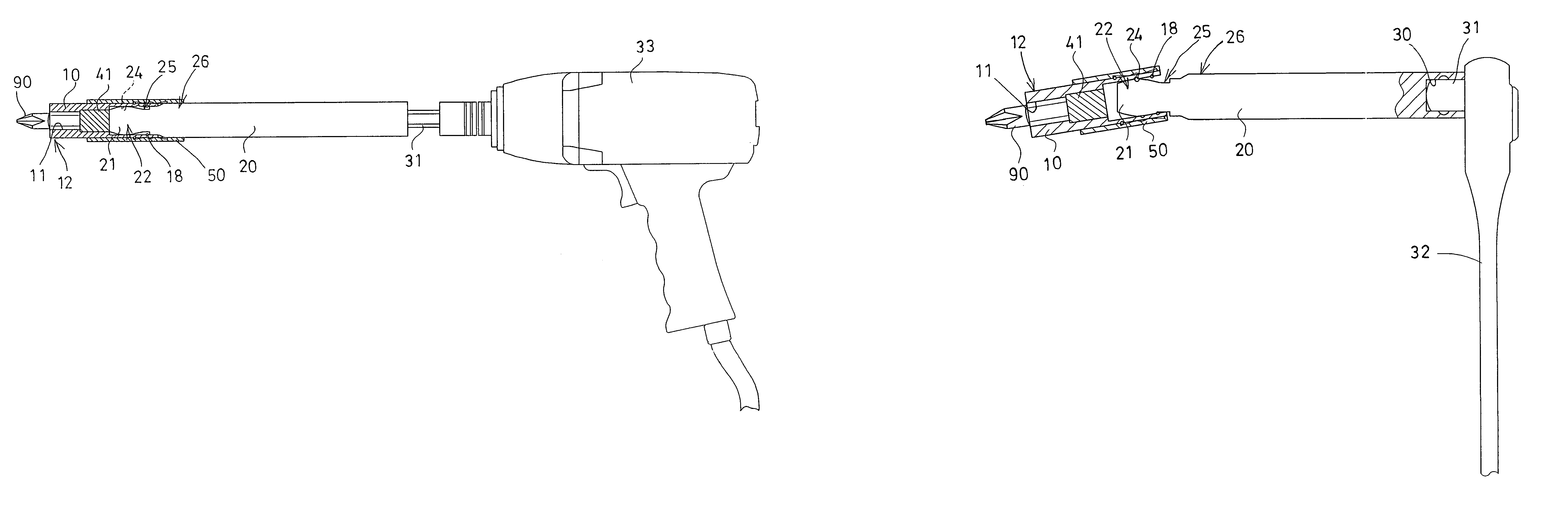
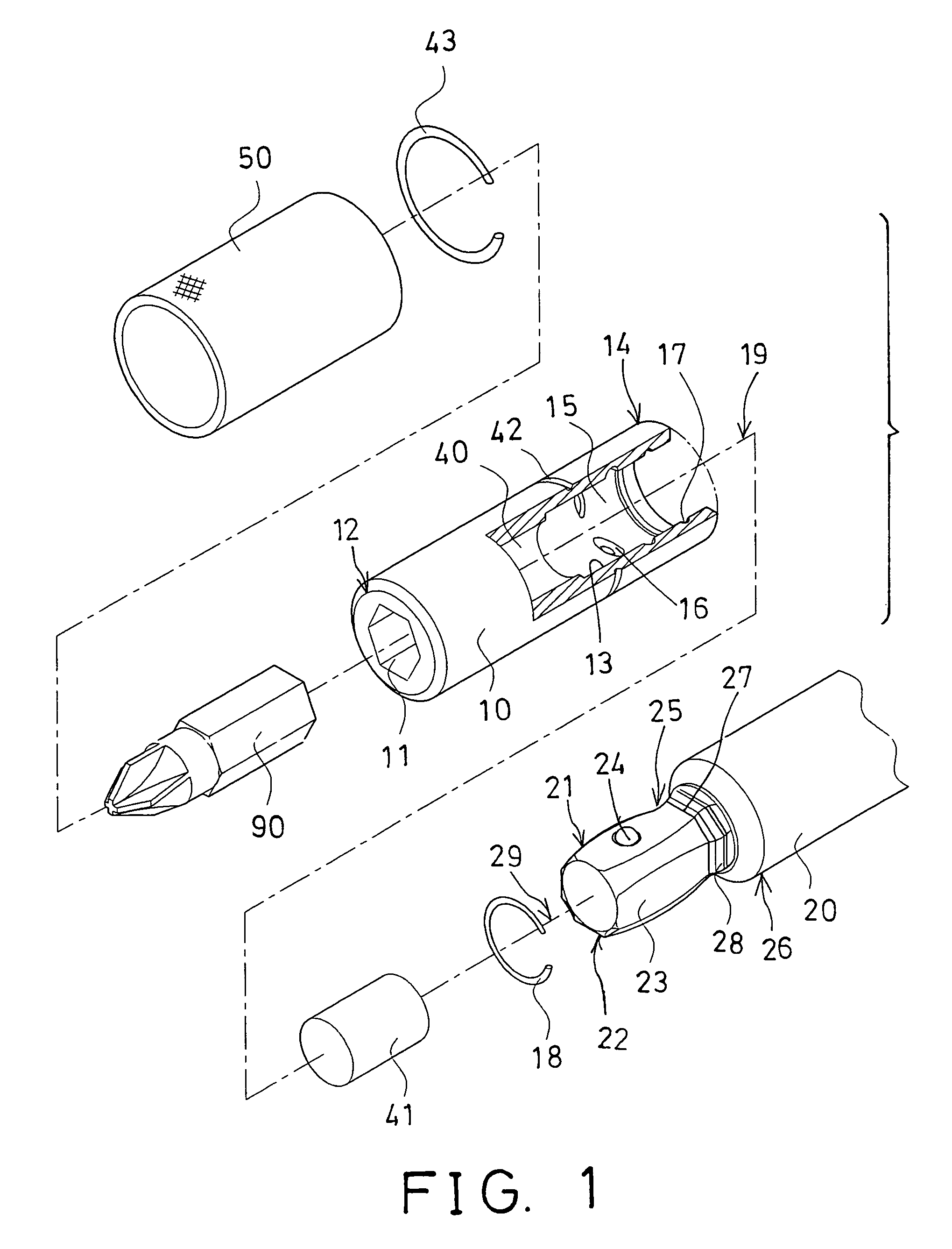
[0023]Referring to the drawings, and initially to FIGS. 1 and 2, a pivotal driving tool assembly in accordance with the present invention comprises a first component 10, such as a follower or a socket 10 including an engaging means or device 11 formed or provided in one end 12 thereof, for engaging with and for driving fasteners, tool extensions, tool bits, or other tool elements (not shown).

[0024]For example, the engaging device 11 of the first component 10 may be an engaging hole 11 (FIGS. 1–6) formed in the end 12 of the first component 10 for receiving or engaging with the fasteners, the tool extensions, the tool bits 90, or other tool elements; or may be a driving stem (not shown) extended from the end 12 of the first component 10 for engaging with the fasteners, the tool extensions, the tool bits, or other tool elements.

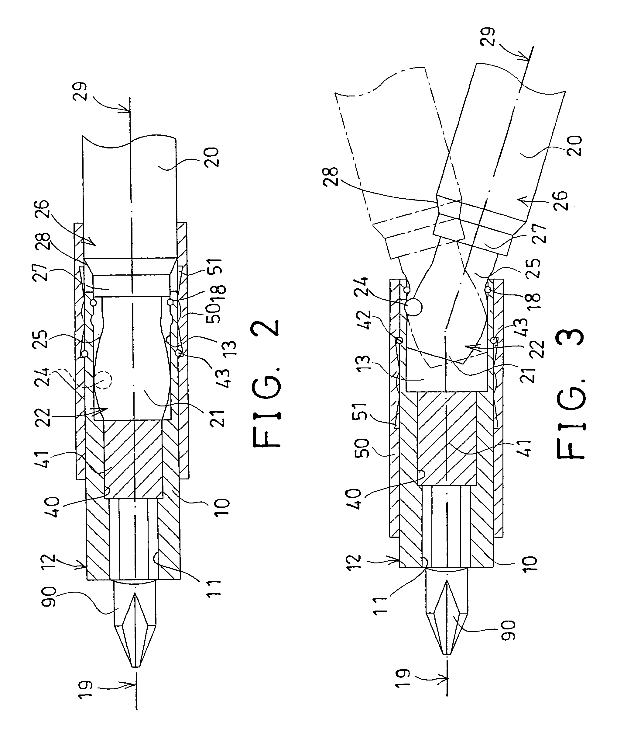
[0025]The first component 10 includes a cavity 13 formed in the other end 14 thereof and having a non-circular cross section formed or defined by three or more...


PUM


Abstract

A pivotal driving tool includes a socket having a non-circular cavity formed by three or more planer side walls, and having an inner retaining ring. A mandrel includes a driving shank having a non-circular cross section for engaging into the socket, to allow the socket to be rotated by the mandrel. The mandrel includes a narrowed neck portion to allow the mandrel to be pivoted relative to the socket, and one or more flat surfaces to solidly anchor the driving shank to the socket. A magnetic member may be disposed in the mandrel, to act on and to pull the driving shank into the cavity of the socket. A barrel may be slidably engaged onto the socket, to engage onto and to be disengaged from the mandrel.

Description

[0001]The present invention is a continuation-in-part of U.S. patent application Ser. No. 10 / 425,374, filed 28 Apr. 2003, pending, to be abandoned.BACKGROUND OF THE INVENTION[0002]1. Field of the Invention[0003]The present invention relates to a pivotal driving tool assembly, and more particularly to a pivotal driving tool assembly having a lock device to prevent tool members from being disengaged from each other.[0004]2. Description of the Prior Art[0005]Typical adapters are provided to attach or to couple various tool members to driving machines or tools, for allowing the tool members to be rotated or driven by the driving machines. For example, U.S. Pat. No. 4,818,157 to Kouvelis discloses one of the typical adapters comprising one or more shafts or tools to be attached or changed and secured to a rotary tool with a chuck. However, the shafts or tools may not be rotated or pivoted or changed to different angular positions relative to the rotary tool.[0006]U.S. Pat. No. 4,995,850 ...

Claims


Application Information

Patent Timeline
Patent Type & Authority Patents(United States)
IPC IPC(8): F16D3/18F16D1/116F16D3/16F16D3/44
CPCF16D1/116F16D3/16Y10S464/901
Inventor CHIOU, LI JIUN
Owner HSIN YING ENTERPRISE
Why Eureka
Try Eureka