Electroluminescent display device

a technology of electroluminescent display device and display device, which is applied in the direction of discharge tube/lamp details, discharge tube luminescnet screens, incadescent body mounting/support, etc., and can solve the problem of rapid temperature ris

Inactive Publication Date: 2006-03-28
SANYO ELECTRIC CO LTD
View PDF16 Cites 49 Cited by
  • Summary
  • Abstract
  • Description
  • Claims
  • Application Information

AI Technical Summary

Problems solved by technology

The above conventional sealing structure is poor in heat dissipation so that the temperature rises rapidly.

Method used


Image

  • Electroluminescent display device
  • Electroluminescent display device
  • Electroluminescent display device

Examples


Embodiment Construction

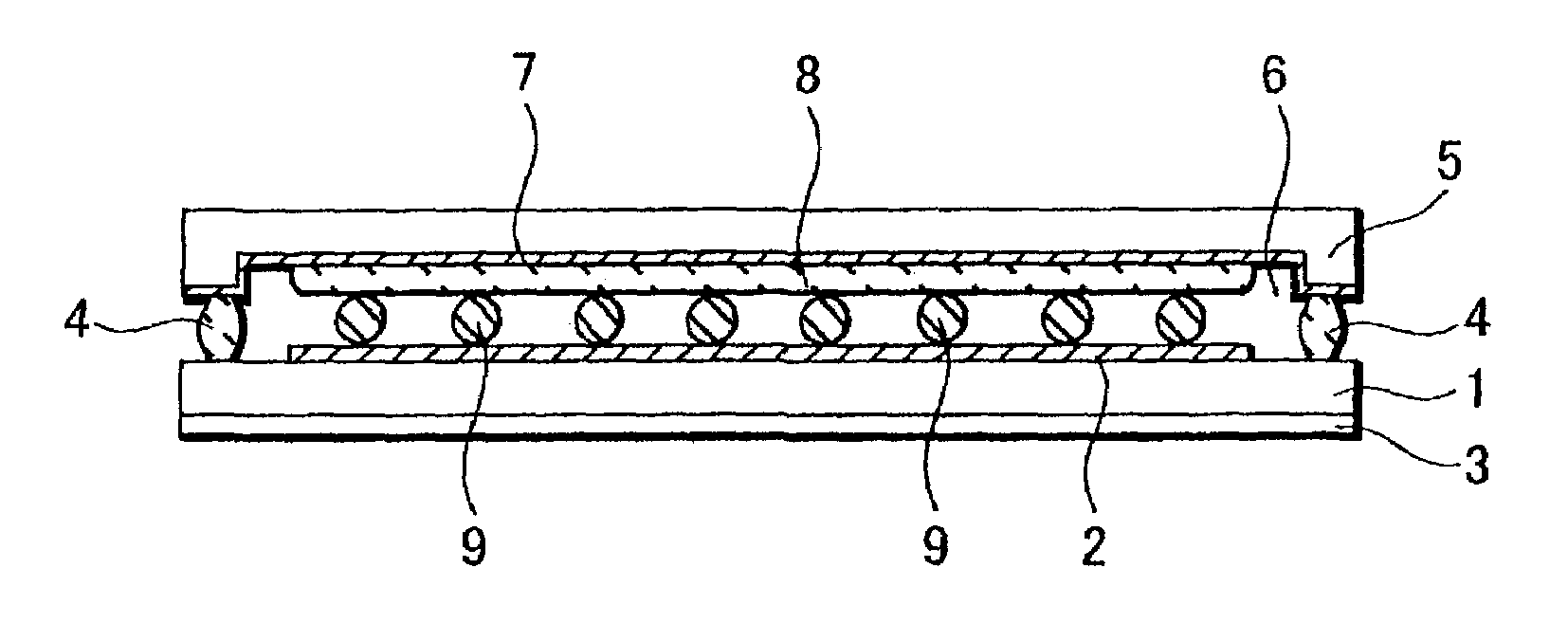
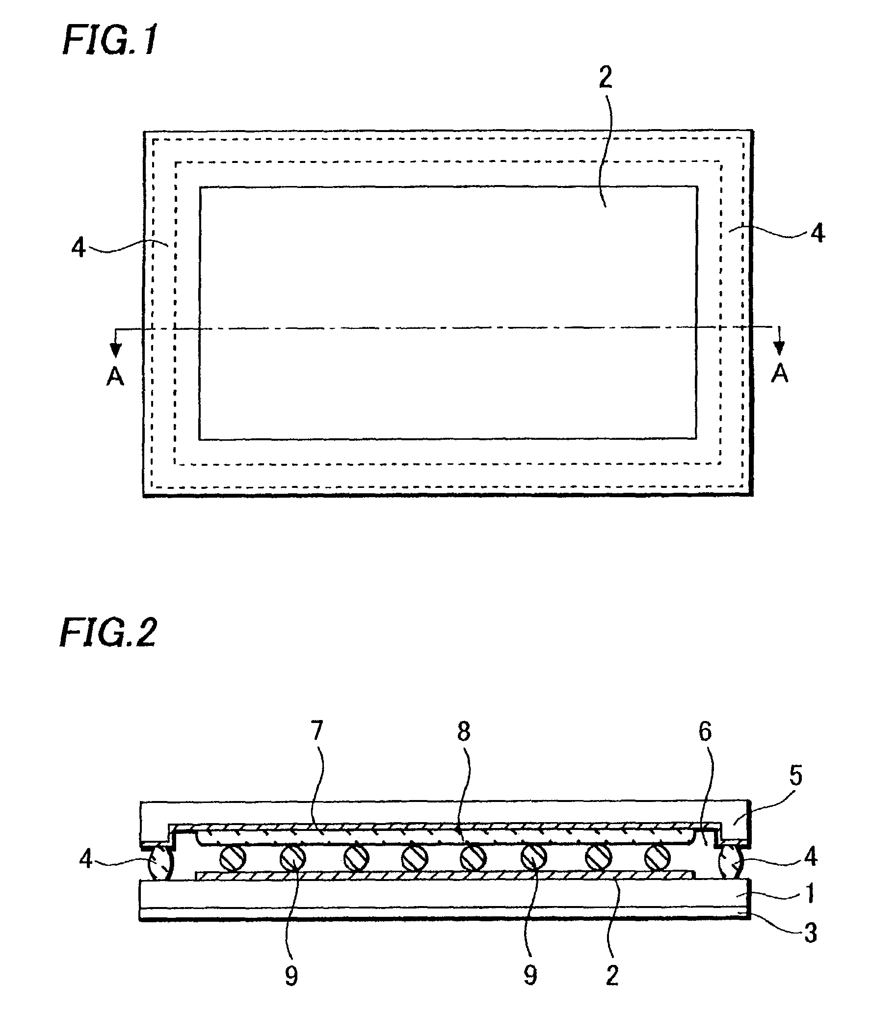
[0015]An embodiment of the invention will be described with reference to the drawings in detail. FIG. 1 is a plan view of an EL display device according to this embodiment.

[0016]FIG. 2 is a cross-sectional view of the device along A—A line of FIG. 1.

[0017]A device glass substrate 1 has a display region having many organic EL elements (not shown) on a surface thereof. The device glass substrate 1 is approximately 0.7 mm in thickness. In this display region, a plurality of pixels is disposed in a matrix and the organic EL element is disposed in each of the pixels.

[0018]The whole surface of the display region is covered by a cathode 2 of the organic EL element. The cathode 2 is made of, for example, A1. The device glass substrate 1 has a polarizer 3 mounted on a back surface thereof.

[0019]The device glass substrate 1 of the above structure is attached to a sealing glass substrate 5 with sealing resin 4 made of an epoxy resin or the like. The sealing glass substrate 5 is approximately 0...


PUM


Abstract

In an organic EL panel having a device glass substrate provided with an organic EL element on a surface thereof, a sealing glass substrate attached to the device glass substrate and a desiccant layer formed on a surface of the sealing glass substrate, spacers are disposed between a cathode of the organic EL element and the desiccant layer. A heat-conductive layer can be formed on a surface of the sealing glass substrate including a pocket portion. The heat-conductive layer can be formed by vapor depositing or sputtering a metal layer such as a Cr layer or an Al layer. This inhibits damaging the organic EL element and increases a heat dissipating ability, thereby inhibiting deterioration of a device property caused by temperature rise.

Description

BACKGROUND OF THE INVENTION[0001]1. Field of the Invention[0002]The present invention relates to a structure of the electroluminescent display device.[0003]2. Description of the Related Art[0004]In recent years, an electroluminescent (hereafter, referred to as EL) display devices with an organic EL element have been receiving an attention as a display device substituting for a CRT and an LCD.[0005]Since the organic EL element is sensitive to moisture, an organic EL display panel having the EL element thereon is covered with a metal cap or a glass cap coated with a desiccant, thereby inhibiting moisture infiltration. FIG. 5 is a cross-sectional view of a structure of a conventional organic EL display panel. A device glass substrate 100 has a display region having many organic EL elements (not shown) on a surface thereof. The whole surface of the display region is covered with a cathode 101 of the organic EL element. The cathode 101 is made of, for example, an Al (aluminum) layer. The...

Claims


Application Information

Patent Timeline
Patent Type & Authority Patents(United States)
IPC IPC(8): H01J1/62H01L51/52
CPCH01L51/5237H01L51/529H10K50/8423H10K50/8428H10K50/846H10K50/87H05B33/04
Inventor YONEDA, KIYOSHI
Owner SANYO ELECTRIC CO LTD
Why Eureka
Try Eureka