Material and device properties modification by electrochemical charge injection in the absence of contacting electrolyte for either local spatial or final states

a charge injection and electrochemical technology, applied in the direction of double layer capacitors, electrical devices, crystal growth processes, etc., can solve the problems of limiting the applicability of devices, limiting the application of materials, and providing problematic structural changes

Active Publication Date: 2007-07-26
BOARD OF RGT THE UNIV OF TEXAS SYST
View PDF16 Cites 38 Cited by
  • Summary
  • Abstract
  • Description
  • Claims
  • Application Information

AI Technical Summary

Problems solved by technology

Prior-art methods for changing these material properties by charge injection either (1) involve electrostatic gate-based charge injection across a dielectric (so charge injection is limited by dielectric breakdown), (2) use an electrolyte that contacts the transformed material (thereby limiting device applicability), or (3) use dopant intercalation (thereby limiting applicable materials and providing problematic structural changes).
This charge injection is that of an ordinary dielectric capacitor, so the amount of charge injection that can be achieved is limited by the breakdown strength of the dielectric.
While enormously useful for submicroscopic electronic devices, this dielectric-based charge injection is unsuitable for macroscopic charge injection in materials having macroscopic external dimensions. X. Xi et al.
(Applied Physics Letters 62, 630 (1993)) demonstrated that TC can be changed by up to 10 K. However, the dielectric-based method of Tc switching used by Xi et al. and by J. Mannhart et al. is not applicable for a macroscopically thick superconducting material.
(Diamond and Related Materials 10, 1705-1708 (2001)) have used under-gate dielectric-based charge injection to modulate electron emission for field emission displays, but find disadvantage in this application as a result of field-induced electron beam spreading and restrictions on the anode voltage.
However, unless the material is a metal or metal oxide catalyst, the electrolyte is a ceramic held at high temperatures (P. E. Tsiakaris, et al., Solid State Ionics 152-153, 721-726 (2002)) prior-art technologies teach that this charge injection can only be accomplished by developing and maintaining contact of the electrolyte with regions of the material where charge injection is desired, which for macroscopic nanoporous materials includes internal surfaces.
However, the maintained contact between the electrode (including both internal and external surfaces) and the electrolyte limits applicability of prior-art methods of non-faradaic electrochemical charge injection.
For example, the surrounding electrolyte for the above described liquid-ion-gated FETs limits their applicability for gas state sensing—since a sensed gas must first dissolve in the electrolyte before it can be detected, which decreases both device response rate and sensitivity and limits detection capabilities to gases that can significantly dissolve in the electrolyte.
Since the electrolyte provides mechanisms for self-discharge, long term energy storage in such a supercapacitor is not possible.
Also, the possibility of charging non-faradaic supercapacitors, removing the electrolyte, and then storing energy in the dry-state supercapacitors has heretofore not been conceived.
This method is limited to the types of materials that can incorporate dopant by a reversible process, preferably at room temperature.
Similarly, this method of charge injection is not useable for non-porous materials having three-dimensional covalent bonding.
Also, substantial dopant intercalation fundamentally changes the structure of the material and can introduce gross structural defects.
As a consequence, de-doping does not completely return the material to the original state.
For such devices, dramatic structural changes are typically associated with dopant intercalation, and these charges are not fully reversed on de-intercalation—which limits cycle life.
The required dopant insertion and de-insertion processes (called intercalation and de-intercalation) result in slow device response, short cycle life, hysteresis (leading to low energy conversion efficiencies), and a device response that depends on both rate and device history.

Method used


Image

  • Material and device properties modification by electrochemical charge injection in the absence of contacting electrolyte for either local spatial or final states
  • Material and device properties modification by electrochemical charge injection in the absence of contacting electrolyte for either local spatial or final states
  • Material and device properties modification by electrochemical charge injection in the absence of contacting electrolyte for either local spatial or final states

Examples


example 1

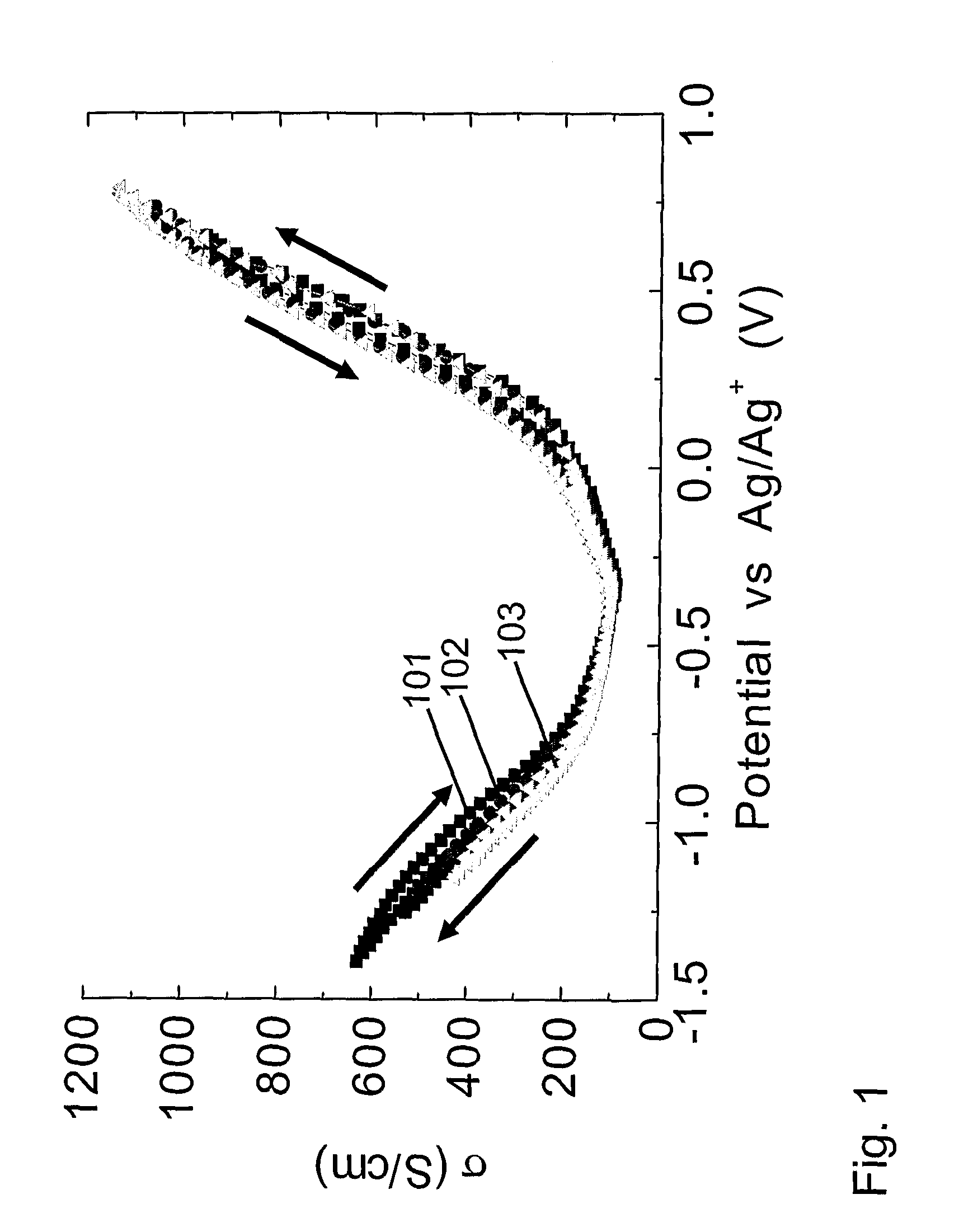
[0218] This example shows that the electrical conductivity of carbon nanotube electrode sheets can be continuously varied by about an order of magnitude using predominately non-faradaic electrochemical charge injection in 1 M NaCl electrolyte

[0219] These nanotube sheets are fabricated analogously to a previously described method (A. G. Rinzler et al., Appl. Phys. A 67, 29 (1998)) by dispersing the carbon nanotubes in surfactant-containing aqueous solution and filtering this nanotube dispersion though through a 47 mm diameter poly(tetrafluoroethylene) filter sheet (Millipore LS) under house vacuum. A sheet of nanotubes collected on the filter paper, which was washed using water and methanol, dried, and then lifted from the filter paper substrate to provide a free-standing SWNT sheet. The density of these nanotube sheets is about 0.3 g / cm3, versus the density of about 1.3 g / cm3 for densely packed nanotubes having close to the observed average nanotube diameter. Hence the void volume ...

example 2

[0224] This example demonstrates that tuning the electrical conductivity of single-wall nanotube sheets over an order-of-magnitude range can also be accomplished using an organic electrolyte, instead of the aqueous electrolyte of Example 1.

[0225] The experimental procedure was exactly the same as for Example 1, except that the 1M NaCl aqueous electrolyte was replaced with either 0.1M TBAPF6 (tetrabutyl ammonium hexafluorophosphate) or 0.1 M TBABF4 (tetrabutyl ammonium tetrafluoroborate) dissolved in acetonitrile and the Ag / AgCl reference electrode was replaced with the Ag / Ag+ reference electrode. There were no significant differences noted between charge-injection tuning of the nanotube sheet conductivity in 0.1M TBAPF6 / acetonitrile and in 0.1 M TBABF4 / acetonitrile.

[0226] Because the potential window of non-faradaic reaction in non-aqueous electrolyte is much wider than for aqueous electrolytes, the potential can be changed up to +1.0V (versus Ag / Ag+) in the positive potential dir...

example 3

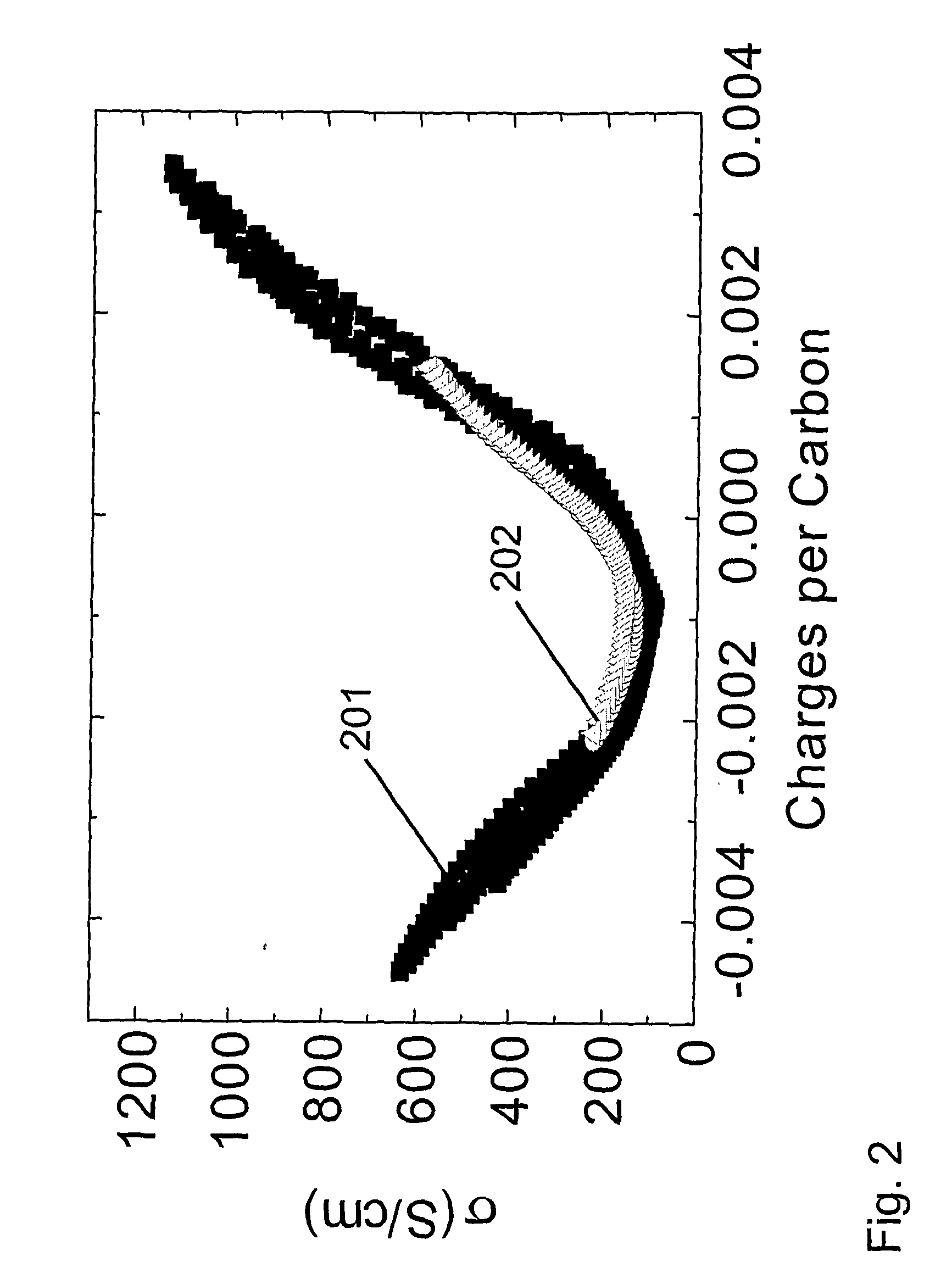
[0229] This example shows that the hysteresis in properties tuning can be significantly reduced if electrical conductivity is varied by charging the amount of injected charge, as opposed to being controlled by changing applied voltage. This point is illustrated for the 0.1 M tetrabutylammonium hexafluorophosphate / acetonitrile electrolyte by comparing the hysteresis in the electrical conductivity versus potential (FIG. 1 and Example 1) with those in FIG. 2, where electrical conductivity is plotted versus charge per carbon in the nanotube working electrode. The decrease that is obtained in hysteresis in going from voltage control of conductivity to charge control is even larger for the aqueous 1 M NaCl electrolyte of Example 1. The data in FIG. 2 also shows the dependence of four-point electrical conductivity upon the amount of injected charge (per carbon) for the nanotube sheet is nearly identical for the 1 M NaCl electrolyte of Example 1 and the 0.1 M tetrabutylammonium hexafluoroph...


PUM

PropertyMeasurementUnit
thicknessaaaaaaaaaa
thicknessaaaaaaaaaa
thicknessaaaaaaaaaa

Abstract

In some embodiments, the present invention is directed to processes for the combination of injecting charge in a material electrochemically via non-faradaic (double-layer) charging, and retaining this charge and associated desirable properties changes when the electrolyte is removed. The present invention is also directed to compositions and applications using material property changes that are induced electrochemically by double-layer charging and retained during subsequent electrolyte removal. In some embodiments, the present invention provides reversible processes for electrochemically injecting charge into material that is not in direct contact with an electrolyte. Additionally, in some embodiments, the present invention is directed to devices and other material applications that use properties changes resulting from reversible electrochemical charge injection in the absence of an electrolyte.

Description

CROSS REFERENCE TO RELATED APPLICATIONS [0001] This application claims priority to U.S. Provisional Application Ser. No. 60 / 550,289, filed Mar. 5, 2004.[0002] This invention was made with partial Government support under Contract No. MDA972-02-C-0044 awarded by the Defense Advanced Research Projects Agency. The Government has certain rights in this invention.FIELD OF THE INVENTION [0003] This invention relates to tuning the electronic, magnetic, and optical properties of materials and devices by non-faradaic electrochemical charge injection, wherein such tuned properties are developed either in the presence or absence of contacting electrolyte, and necessarily maintained in the absence of directly contacting electrolyte. BACKGROUND OF THE INVENTION [0004] It is well known that charge injection can change the magnetic, electronic and optical properties of materials. Prior-art methods for changing these material properties by charge injection either (1) involve electrostatic gate-base...

Claims


Application Information

Patent Timeline
Patent Type & Authority Applications(United States)
IPC IPC(8): C02F1/461
CPCB82Y30/00H01G11/06H01G9/155H01G11/34H01G11/42H01M4/8605H01M4/92H01M4/926H01M8/1002H01M8/1004Y02E60/13Y02E60/521H01L29/45H01L29/4908H01G9/058H01M8/1007Y02E60/50H01G11/36H01G11/22
Inventor SUH, DONG-SEOKBAUGHMAN, RAY HENRYZAKHIDOV, ANVAR ABDULAHADOVIC
Owner BOARD OF RGT THE UNIV OF TEXAS SYST
Why Eureka
Try Eureka