Contact potential difference sensor to monitor oil properties

a technology of contact potential and oil properties, which is applied in the direction of resistance/reactance/impedence, instruments, transportation and packaging, etc., can solve the problems of inability to be used in many applications, inability to sense other than ferromagnetic debris, and gross insensitivity to critical operating conditions to which oil is subj

Active Publication Date: 2006-03-28
GEORGIA TECH RES CORP
View PDF11 Cites 24 Cited by
  • Summary
  • Abstract
  • Description
  • Claims
  • Application Information

AI Technical Summary

Benefits of technology

[0006]It is therefore an object of the invention to provide an i

Problems solved by technology

The above described prior art systems suffer from numerous disadvantages, such as, gross insensitivity to critical operating conditions to which oil is subjected, inability to be utilized in many applications du

Method used


Image

  • Contact potential difference sensor to monitor oil properties
  • Contact potential difference sensor to monitor oil properties
  • Contact potential difference sensor to monitor oil properties

Examples


Embodiment Construction

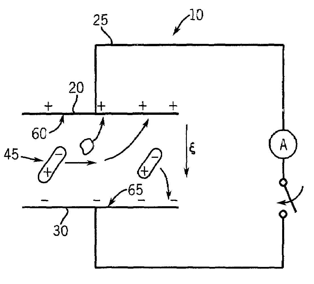
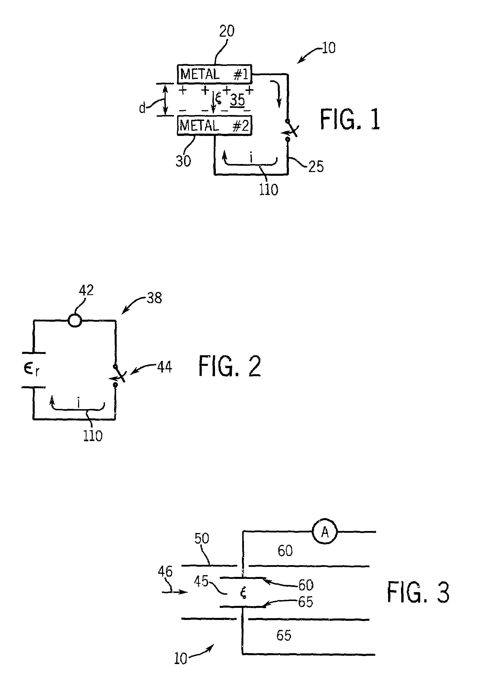
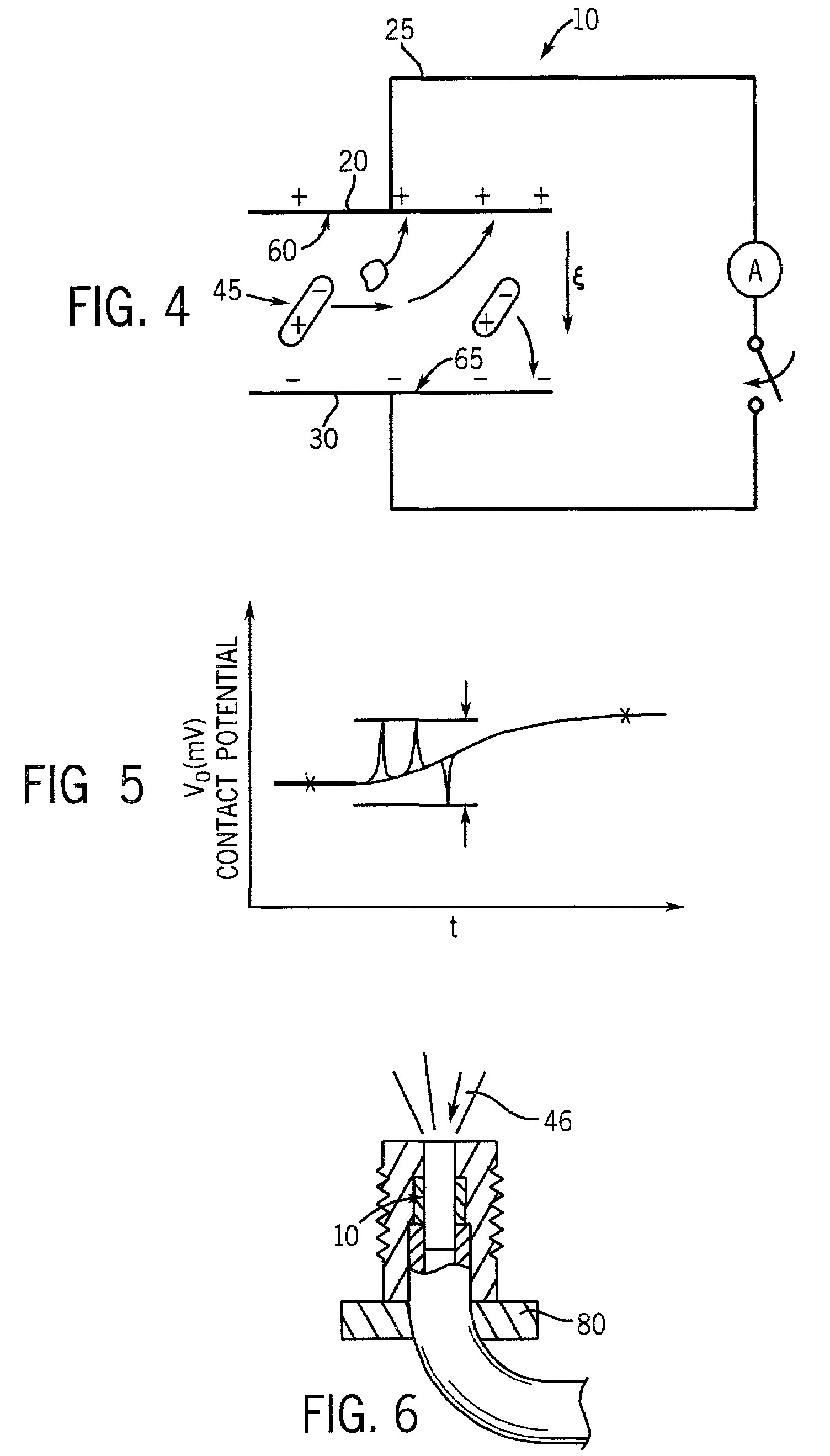
[0025]An illustration of the principals used to monitor properties of oils, other fluids and even particular gaseous environments is shown schematically in FIG. 1. A contact potential sensor 10 is illustrated wherein a first conductive material 20, such as a first metal, is electrically coupled by a connection 25 to a second conductive material 30, such as a second metal. In particular the sensor 10 is a non-vibrating contact potential difference probe. An electric field, {right arrow over (∈)}, arises between the first conductive material 20 and the second conductive material 30 when the two materials are electrically connected, and the electric field, {right arrow over (∈)}, will form when the Fermi energies of the two materials 20 and 30 are equilibrated. The strength of the electric field, {right arrow over (∈)}, will depend on the dielectric properties, a relative dielectric constant, ∈r, of the material disposed in gap 35 between the two materials 20 and 30. In general, the se...


PUM


Abstract

A method and system for contact potential sensing of dielectric properties of a fluid. The method and system include a contact potential sensor, an open or closed loop for passing a fluid past the sensor, measuring a contact potential to characterize dielectric properties of the fluid and outputting the dielectric property information for analysis and response thereto.

Description

[0001]This application claims the benefit of Provisional Application Ser. No. 60 / 279,596, filed Mar. 29, 2001.[0002]This invention was made in part with U.S. Government support under a grant from the Office of Naval Research Contract No. N000140010374. The U.S. Government has certain rights in this invention.FIELD OF THE INVENTION[0003]The present invention is directed generally to a method and system for monitoring oil properties. More particularly the invention is directed to a method and system using a contact potential sensor to monitor properties of flowing oilBACKGROUND OF THE INVENTION[0004]A variety of mechanical systems, such as engines, require means to monitor the quality of oil used for lubrication and other functionalities. A number of prior art methods exist for performing this function, including, for example (1) an odometer monitor to time out the useful life of oil based on general lifetime assumptions, (2) a magnetic field sensor for sensing density of ferromagneti...

Claims


Application Information

Patent Timeline
IPC IPC(8): G08B21/00G01N27/00G01N27/22G01N33/28
CPCG01N27/002G01N33/2888G01N27/221
Inventor DANYLUK, STEVENZHARIN, ANATOLY
Owner GEORGIA TECH RES CORP
Why Eureka
Try Eureka