Image forming apparatus with heat exhausting means for exhausting air from around a fixing unit and a delivery tray

a technology of heat exhausting and forming apparatus, which is applied in the direction of electrographic process apparatus, instruments, optics, etc., can solve the problems of requiring the copying machine to be shut down for a long time and not only a long time for maintenance operations, but also a long time for the fan

Inactive Publication Date: 2006-03-28
CANON KK
View PDF10 Cites 30 Cited by
  • Summary
  • Abstract
  • Description
  • Claims
  • Application Information

AI Technical Summary

Benefits of technology

[0015]An object of the present invention is to provide an image forming apparatus that can exhaust the heat generated by fixing means that generates heat to prevent the delivered sheet adhesion due to high temperature from occurring.
[0023]The image forming apparatus with heat exhausting means according to the present invention may further comprise heat exhaust control means for controlling, while the sheet is transported in the sheet transport path, the heat exhausting means in such a way as to reduce an air exhaust amount of the heat exhausting means as the sheet approaches from the fixing means to the delivering and stacking means.

Problems solved by technology

In addition, the above-described arrangements of the fans not only require a long time for maintenance operations but also require the copying machine to be shut down for a long time (i.e. downtime is long).

Method used


Image

  • Image forming apparatus with heat exhausting means for exhausting air from around a fixing unit and a delivery tray
  • Image forming apparatus with heat exhausting means for exhausting air from around a fixing unit and a delivery tray
  • Image forming apparatus with heat exhausting means for exhausting air from around a fixing unit and a delivery tray

Examples


first embodiment

(Copying Machine )

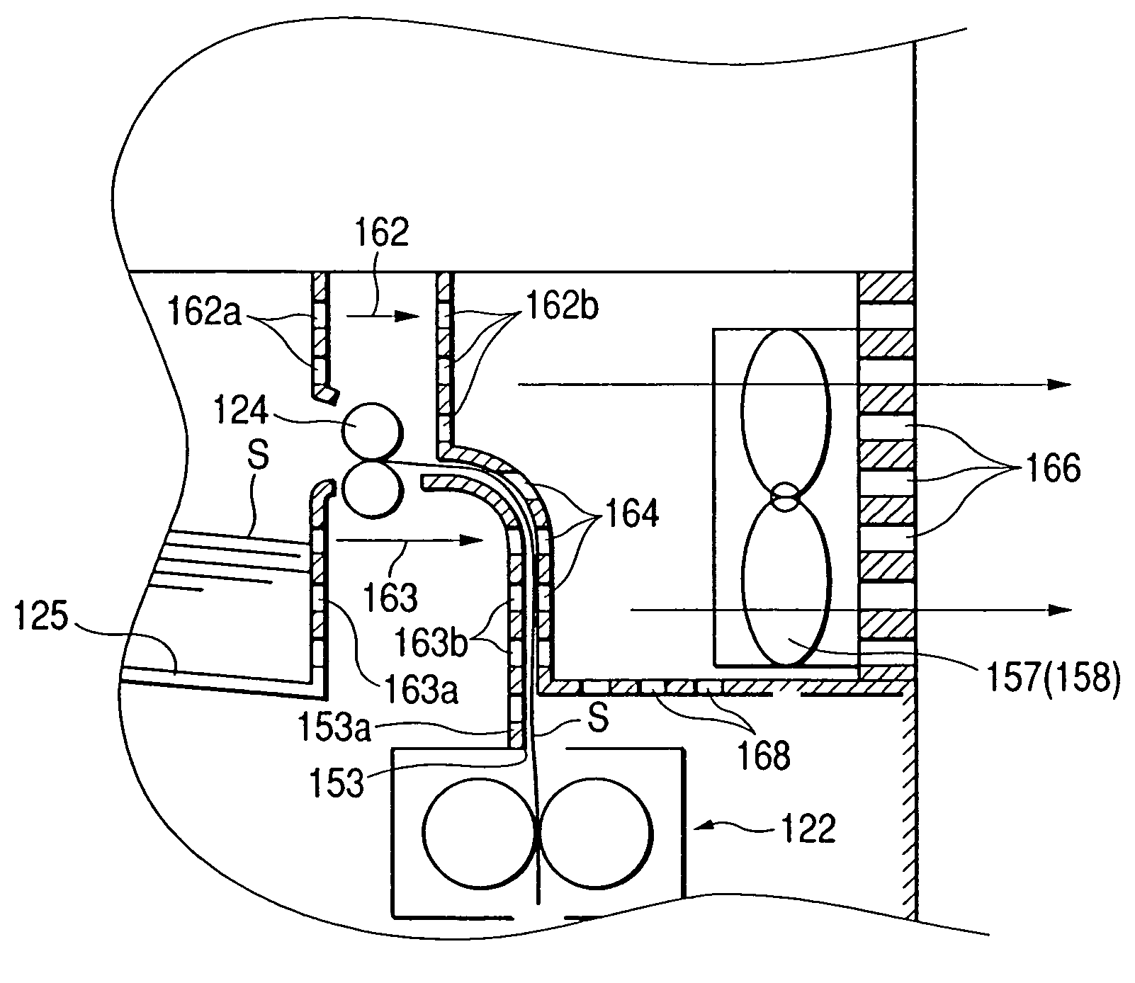
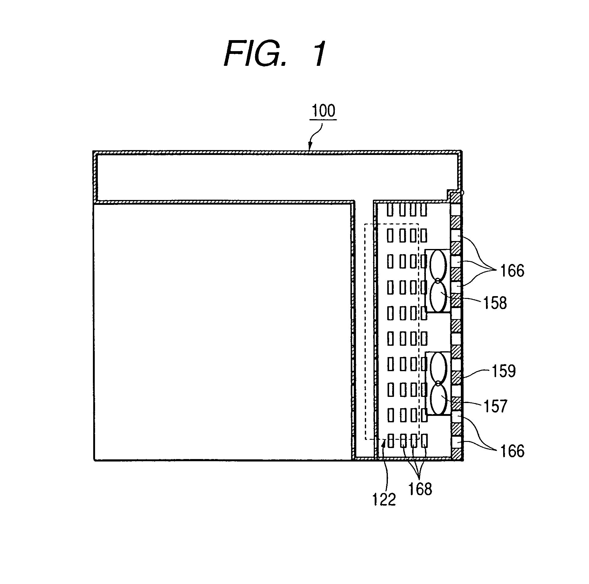
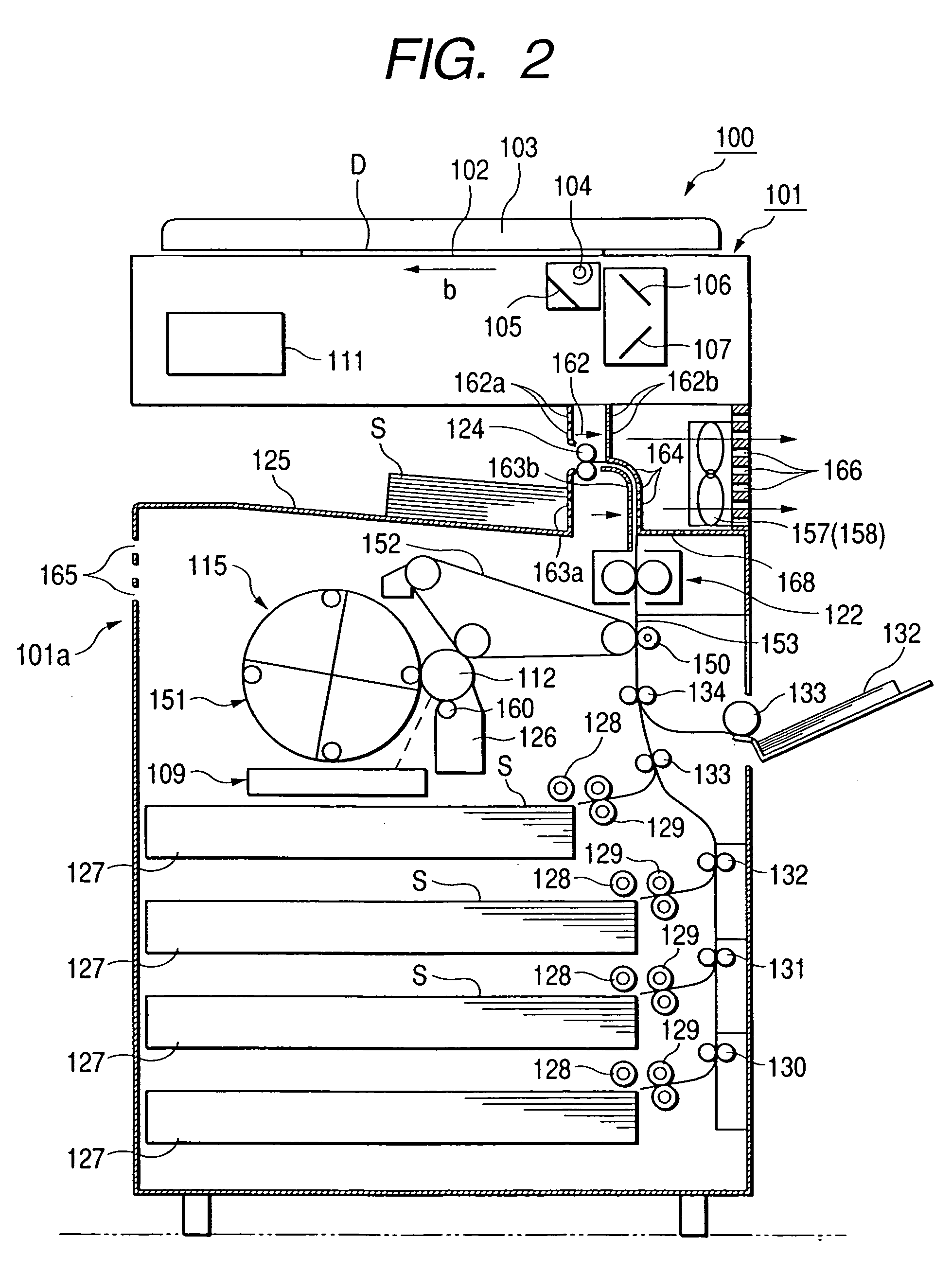
[0038]In the following, a copying machine according to a first embodiment of the invention will be described with reference to FIGS. 1, 2 and 3. FIG. 1 is a plan view of the copying machine. FIG. 2 is a cross sectional front view of the copying machine. FIG. 3 is a detailed view showing a portion around a fixing device 122 and a delivery portion 125.

[0039]As shown in FIG. 2, the copying machine 100 is provided with a document stand 102 composed of a transparent glass plate that is fixed to the top portion of the main body 101 of the machine. A document pressure cover 103 is configured to press a document D that is being placed in a predetermined position on the document stand 102 with its image surface facing downward, against the document stand 102 to immobilize it. Beneath the document stand 102, there is provided an optical system composed of a lamp 104 for illuminating the document D, reflection mirrors 105, 106 and 107 for directing a reflected light image of ...

second embodiment

(Copying Machine )

[0050]In the following, a copying machine according to a second embodiment of the invention will be described with reference to FIGS. 4 and 5. FIG. 4 is a plan view of the copying machine and FIG. 5 is a cross sectional front view of the copying machine.

[0051]The copying machine 200 according to the second embodiment differs from the copying machine 100 according to the first embodiment in that a jammed sheet clearance door 159 is provided on the main body 101 of the apparatus in such a way that it is openable and closable and heat exhaust fans 157 and 158 are provided on that jammed sheet clearance door 159. In the copying machine 200 according to the second embodiment, the same parts as those in the copying machine 100 according to the first embodiment are designated with the same reference signs and the descriptions thereof will be omitted.

[0052]The heat exhausting fans 157 and 158 are provided on the inner surface 159a of the jammed sheet clearance door 159 tha...

third embodiment

(Copying Machine )

[0056]In the following, a copying machine according to a third embodiment of the invention will be described with reference to FIGS. 6 and 7. FIGS. 6 and 7 are cross sectional views showing a portion including heat exhausting fans of the copying machine 300 according to the third embodiment. In the copying machine 300 according to the third embodiment, the same parts as those in the copying machine 100 according to the first embodiment are designated with the same reference signs and the descriptions thereof will be omitted.

[0057]In the copying machine 300 according to the third embodiment, heat exhausting fans 157 and 158 are so controlled by a heat exhaust control portion 169 that their rotating speed can be varied in accordance with transport timing of sheets.

[0058]As the copying machine 300 performs an image forming operation, the heat exhausting fans 157 and 158 exhaust air in the surroundings of the fixing device 122 and the delivery portion 125 in the right ...


PUM


Abstract

A copying machine 100 is provided with an image forming portion 115 for forming a toner image on a sheet, a fixing device 122 for applying heat to the sheet to fix the toner image on the sheet, a delivery portion 125 on which the sheet is delivered and stacked, heat exhausting fans 157 and 158 provided in the vicinity of the fixing device 122 and the delivery portion 125 for exhausting air in the surroundings of those 122, 125 from the right side 101b of the main body 101. There is provided air vents 162, 163 and 164 between the fixing device 122 and the heat exhausting fans 157, 158 and between the delivery portion 125 and the heat exhausting fans 157 and 158. Thus, heat of the fixing device 122 is exhausted to avoid the delivered sheet adhesion caused by the high temperature.

Description

TECHNICAL FIELD[0001]The present invention relates to an image forming apparatus, such as a copying machine or a laser beam printer etc., for forming a toner image on a sheet.BACKGROUND ART[0002]There are conventional image forming apparatus, such as copying machines or laser beam printers (LBP), which form images on sheets.[0003]In FIG. 8, a copying machine as an example of such an image forming apparatus is shown. The copying machine 10 is provided with a document stand 2 composed of a transparent glass plate that is fixed to the top portion of the main body 1 of the copying machine 10. A document pressure cover 3 is configured to press a document D that is being placed at a predetermined position on the document stand 2 with its image surface facing downward, against the document stand 2 to immobilize it. Beneath the document stand 2, there is provided an optical system composed of a lamp 4 for illuminating the document D, reflection mirrors 5, 6 and 7 for directing a reflected l...

Claims


Application Information

Patent Timeline
Patent Type & Authority Patents(United States)
IPC IPC(8): G03G21/20
CPCG03G21/206G03G15/6573
Inventor AWAYA, TETSURO
Owner CANON KK
Why Eureka
Try Eureka