Fuel injection system and method for ascertaining a needle stroke stop in a fuel injector

a fuel injection system and fuel injection technology, applied in the direction of fuel injection apparatus, charge feed system, electric control, etc., can solve the problems of actuator stroke decline with increase in lifetime, mechanical and electrical variables and relationships in the injector may change, and achieve the effect of low initial voltag

Inactive Publication Date: 2010-03-11
ROBERT BOSCH GMBH
View PDF13 Cites 24 Cited by
  • Summary
  • Abstract
  • Description
  • Claims
  • Application Information

AI Technical Summary

Benefits of technology

[0005]Example embodiments of the present invention provide a fuel injection system in which the reaching of a stroke stop and / or the instant at which the stroke stop is reached may be ascertained in a particularly simple manner, i.e., in a manner that does not waste time and resources but is nevertheless highly accurate. Example embodiments of the present invention provide a method, which also allows particularly simple detection of the reaching of a stroke stop and / or the ascertaining of the instant at which the stroke stop is reached, i.e., in a manner that does not waste time and resources but is nevertheless highly accurate.
[0006]According to example embodiments of the present invention, the reaching of the stroke stop is ascertained by analyzing the voltage characteristic of the voltage applied to the piezoelectric actuator during a pause in energization. Oscillations in the voltage characteristic in particular that result when the nozzle needle is not in contact with a stroke stop should be evaluated and analyzed. The results of ascertaining this (stroke stop is not reached, stroke stop is reached later than estimated, stroke stop is not reached) may be taken into account in regulating the quantity of fuel to be injected. Therefore, it is possible to have a positive influence on the combustion of fuel in the combustion chamber of the internal combustion engine and combustion takes place quietly with low consumption and low exhaust.
[0009]Example embodiments allow exact, time-based determination of the break or of the voltage peak in the proposed manner, even when there is measurement noise or pressure-dependent dynamic effects within the injector, which may result in extreme rounding of the voltage characteristic, for example.

Problems solved by technology

The mechanical and electrical variables and relationships in the injector may change due to manufacturing tolerances and wear over the entire lifetime of a fuel injector and due to fluctuating operating temperatures.
For example, the actuator stroke may decline with an increase in lifetime, so that the nozzle needle opens later and closes sooner, resulting in injection of less fuel than desired.

Method used


Image

  • Fuel injection system and method for ascertaining a needle stroke stop in a fuel injector
  • Fuel injection system and method for ascertaining a needle stroke stop in a fuel injector
  • Fuel injection system and method for ascertaining a needle stroke stop in a fuel injector

Examples


Embodiment Construction

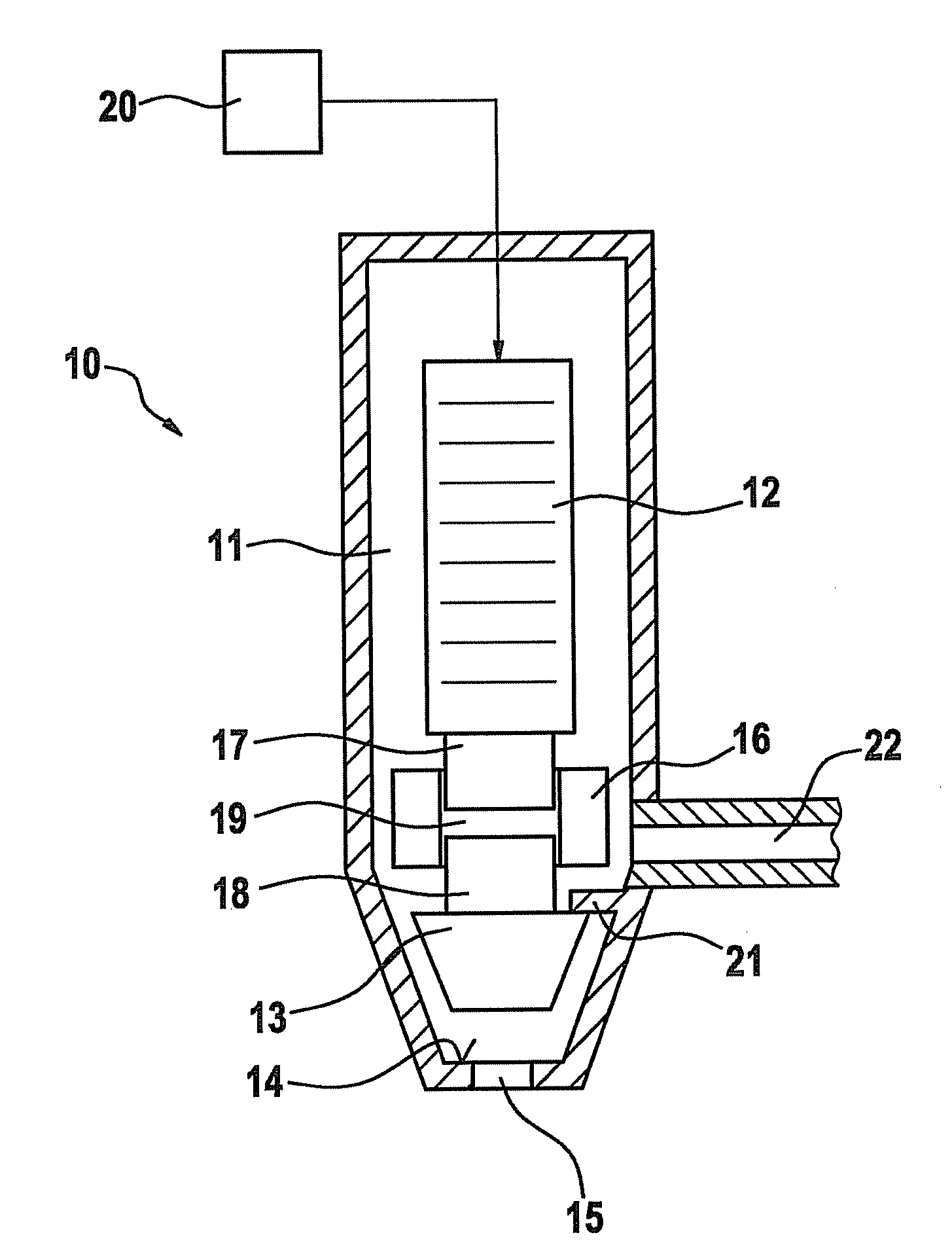
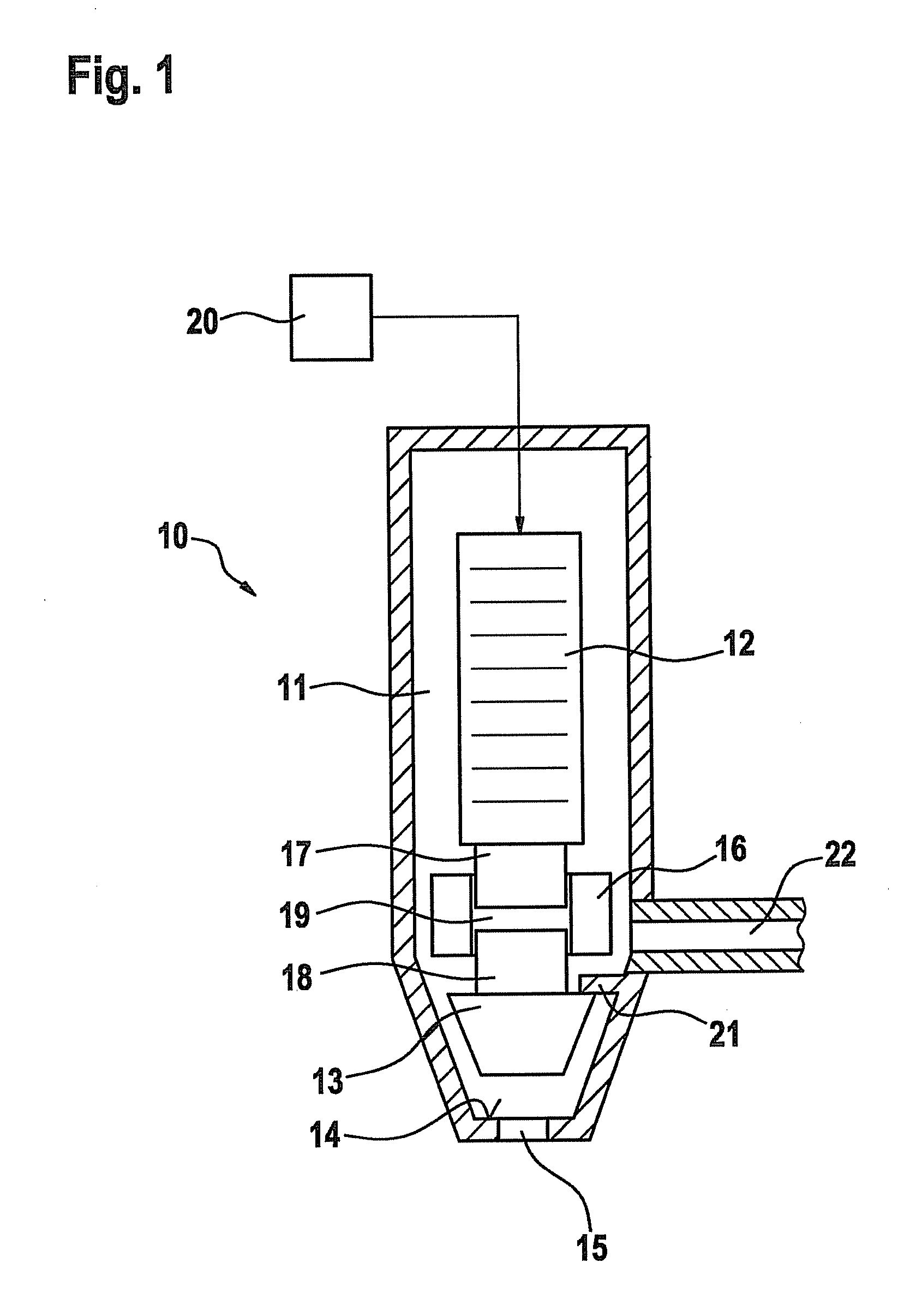
[0022]FIG. 1 shows a fuel injector 10 for an internal combustion engine equipped with a piezoelectric actuator 12. Fuel injector 10 is referred to as an injector, which injects fuel 11, e.g., gasoline or diesel, into an intake manifold and / or directly into a combustion chamber of the internal combustion engine. Piezoelectric actuator 12 is triggered by a control unit 20, as indicated by the arrow in FIG. 1. In addition, fuel injector 10 has a nozzle element having a nozzle needle 13, which may sit on a valve seat 14 in the interior of the housing of fuel injector 10. Valve seat 14 surrounds a nozzle opening 15. Injector 10 may of course also have more than one nozzle opening 15, as depicted here. Furthermore, the nozzle openings may also be formed on the side walls of the housing of valve 10.

[0023]If nozzle needle 13 is raised by valve seat 14, fuel 11 may flow through nozzle opening 15, so that fuel injector 10 is opened and fuel 11 is injected. This state is depicted in FIG. 1. If...


PUM


Abstract

In fuel injection system having at least one fuel injector and a control unit for triggering the injector, each injector has a piezoelectric actuator, a nozzle element having at least one nozzle opening and at least one movable nozzle needle for selectively closing and opening the at least one nozzle opening, a hydraulic coupling element, which is connected between the piezoelectric actuator and the nozzle needle, and at least one stroke stop, against which the nozzle needle rests in its completely open and / or completely closed position. To be better able to ascertain when the stroke stop is reached in such injectors, the needle stroke stop is ascertained during an energization pause of the piezoelectric actuator by analyzing a voltage signal applied to the piezoelectric actuator. Oscillations of the voltage signal during the energization pause are preferably analyzed. To this end, regression lines are drawn through the voltage characteristic, a correlation coefficient of the regression lines to the voltage characteristic is ascertained and a needle stroke stop is detected on the basis of the correlation coefficient.

Description

FIELD OF THE INVENTION[0001]The present invention relates to a fuel injection system and a method for ascertaining a needle stroke stop in a fuel injector.BACKGROUND INFORMATION[0002]Fuel injectors for injecting diesel or gasoline into the intake manifold or directly into the combustion chamber of an internal combustion engine are known from the related art. The injectors may be operated by piezoelectric actuators to meet high dynamic requirements. A hydraulic coupler is connected between the piezoelectric actuator and a nozzle needle of the injector for temperature equalization and for translation. With the known injectors of the CRI-PDN type (common rail injector-piezo direct needle) from Robert Bosch GmbH, the nozzle needle is set in motion more or less directly by the piezoelectric actuator, i.e., the movement of the nozzle needle follows the actuator stroke in a first approximation. The actuator stroke is in turn proportional to the trigger voltage in a first approximation at a...

Claims


Application Information

Patent Timeline
Patent Type & Authority Applications(United States)
IPC IPC(8): F02M51/00
CPCF02D41/2096F02D2041/2051
Inventor RAU, ANDREASBECKER, OLIVERTONNER, ERIK
Owner ROBERT BOSCH GMBH
Why Eureka
Try Eureka