
Tray guide mechanism for an optical disc drive

Inactive Publication Date: 2006-03-28
SAMSUNG ELECTRONICS CO LTD
View PDF6 Cites 30 Cited by
  • Summary
  • Abstract
  • Description
  • Claims
  • Application Information

AI Technical Summary

Benefits of technology

[0019]Accordingly, it is an object of the present invention to provide a tray guide mechanism of an optical disc drive, which is easily inserted into and ejected from a narrow disc drive.
[0042]According to an aspect of the invention, the spacer that prevents a bumping of the guide rail against screw holes by which a hard disc drive is installed into a computer, is installed at a sidewall of the lower case to a predetermined thickness.
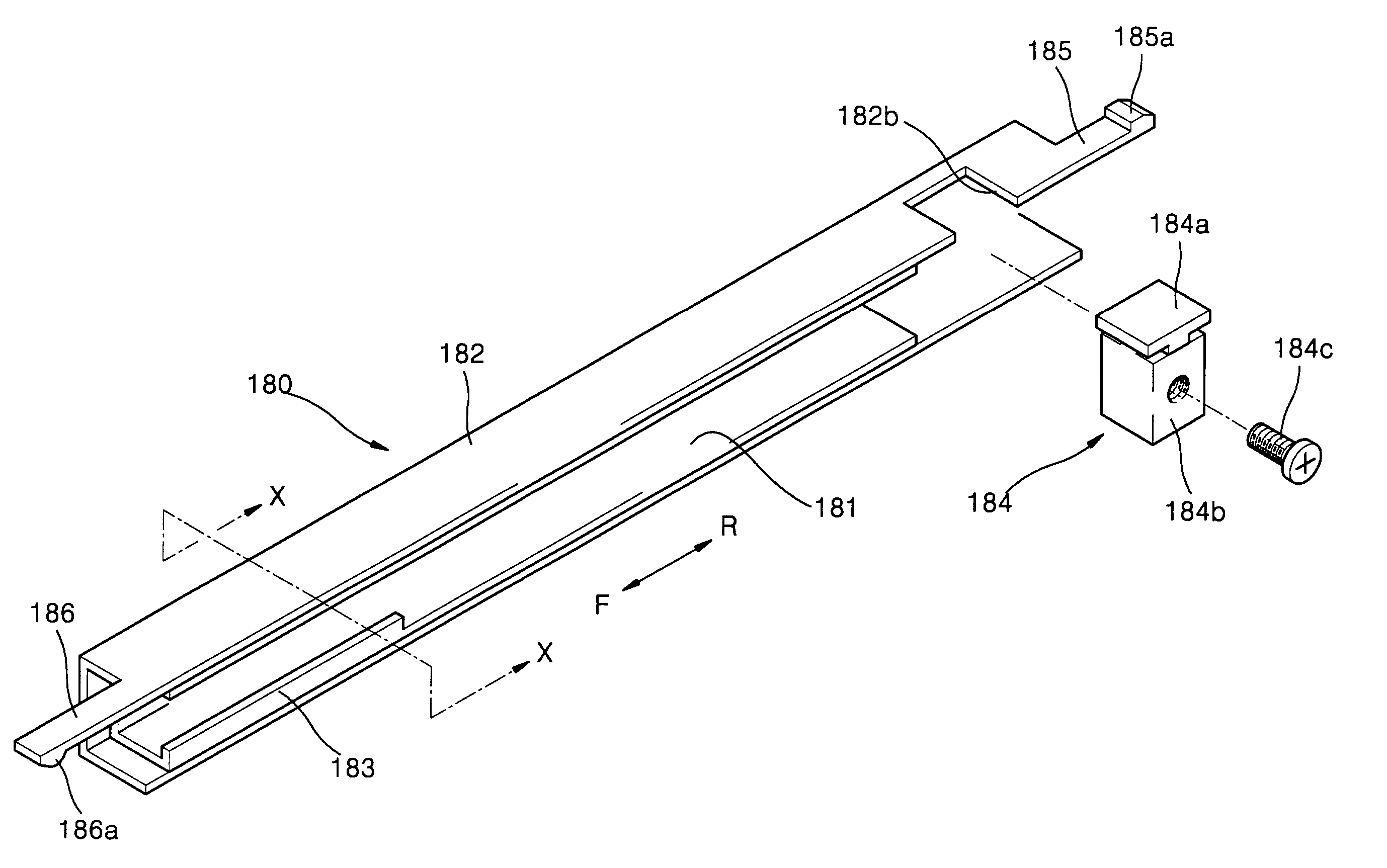
[0043]According to an aspect of the invention, the tray guide mechanism is configured so that the guide rail is installed in contact with a rail and the rail cover. The guide rail is strengthened to firmly support the tray and is installed in a narrow space of a compact optical disc drive. Also, the tray guide mechanism includes the vertical and horizontal restrainers that prevent vertical and horizontal vibration or swaying of the tray.

Problems solved by technology

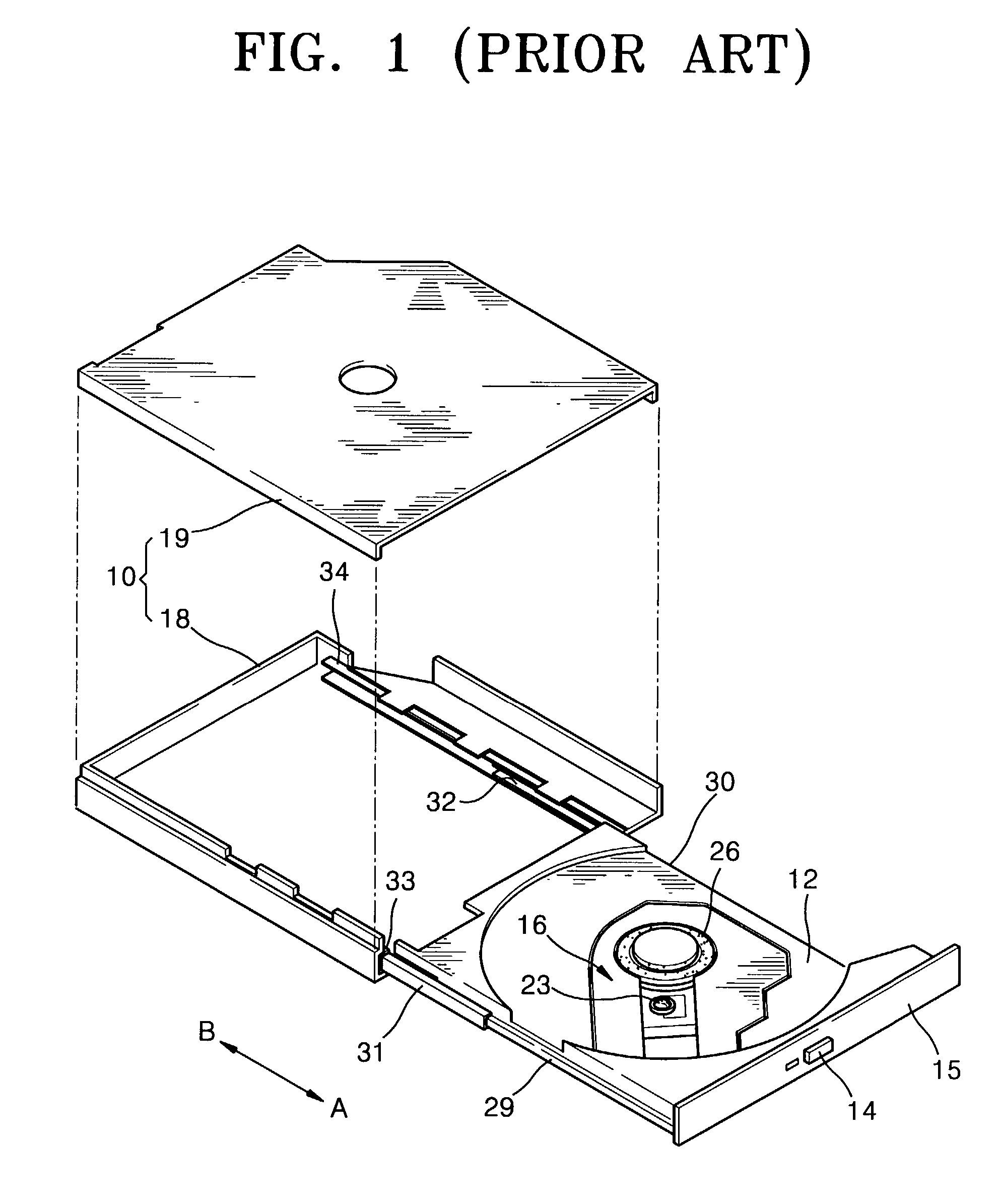
The swaying of the tray 12 may result in errors in reading data stored by the optical pickup unit 23.

Method used


Image

  • Tray guide mechanism for an optical disc drive
  • Tray guide mechanism for an optical disc drive
  • Tray guide mechanism for an optical disc drive

Examples


Embodiment Construction

[0061]Reference will now be made in detail to the present preferred embodiments of the present invention, examples of which are illustrated in the accompanying drawings, wherein like reference numerals refer to like elements throughout.

[0062]FIG. 5 is a cutaway perspective view of an optical disc drive adopting a tray guide mechanism, according to an embodiment of the present invention. The optical disc drive of FIG. 5 includes a housing 100 made of a lower case 110 and an upper case 120, and a tray 130 that is installed to be inserted into and ejected from the housing 100. The housing 100 is fixed in an electronic appliance having a slim optical disc drive, e.g., a computer, a notebook computer, etc. The tray 130 is combined with a main base 140. In the main base 140 is installed a spindle motor 150 that rotates a disc, an optical pickup unit 160 that is used to reproduce data recorded on the rotating disc, and a shift unit (not shown) that moves the optical pickup unit 160 backwar...


PUM


Abstract

A tray guide mechanism for an optical disc drive guides a backward and forward movement of a tray installed to slide into and out of a housing made of a lower case and an upper case. The tray guide mechanism includes guide rails installed to slide into and out of both sides of the upper case, a guide rail supporting unit installed at both sides of the lower case, to prevent the guide rails from deviating from a backward and forward moving path, and rail combiners formed at both sides of the tray in a moving path of the tray, and combined with the guide rails to slide into the guide rails. The tray guide mechanism also includes a forward moving distance limiting unit to limit a moving distance of the tray and the guide rails in a direction to which the tray and the guide rails project to prevent the tray from detaching from the housing. The tray guide mechanism also includes vertical and horizontal restrainers to prevent vertical and horizontal movement of the tray. The guide rails are shaped such that the rail combiners are inserted thereinto, and includes rails which slide into and out of the rail combiners while remaining in contact with the rail combiners. The guide rails also include rail covers which are fixed to outer sides of the rails and slide into and out of the lower case while being in contact with the lower case. The tray guide mechanism is configured such that a guide rail is installed in contact with a rail and a rail cover, and thus is strengthened to firmly support the tray and is installed in a narrow space of the compact optical disc drive. Also, the tray guide mechanism includes the vertical and horizontal restrainers that prevent vertical and horizontal vibration or swaying of the tray.

Description

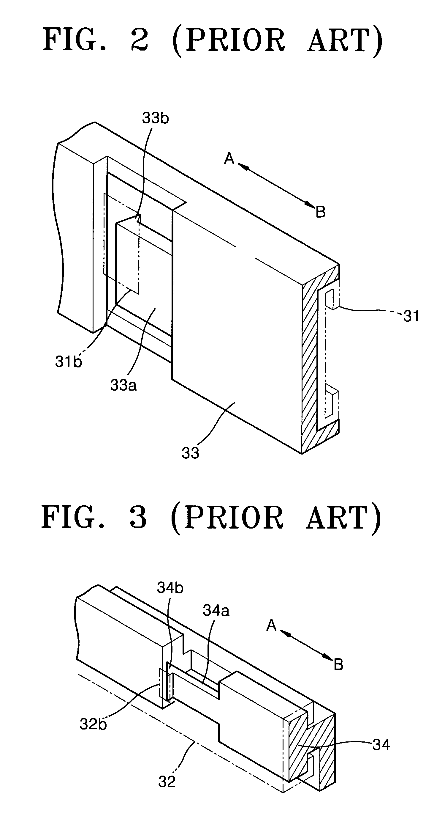
CROSS-REFERENCE TO RELATED APPLICATION[0001]This application claims the benefit of Korean Application No. 2001-71097, filed Nov. 15, 2001, in the Korean Intellectual Property Office, the disclosure of which is incorporated herein by reference.BACKGROUND OF THE INVENTION[0002]1. Field of the Invention[0003]The present invention relates to an optical disc drive, and more particularly, to a tray guide mechanism that is easily inserted into and ejected from a narrow chassis of a slim optical disc drive.[0004]2. Description of the Related Art[0005]In general, an optical disc drive is an apparatus that is used to record or reproduce data to / from an optical recording medium such as a compact disc (CD) or a digital versatile disc (DVD) by irradiating light thereon. The optical disc drive is mainly used in a computer. Particularly, an ultra thin optical disc drive is required in a notebook-sized personal computer.[0006]FIG. 1 is a view of an example of a conventional optical disc drive which...

Claims


Application Information

Patent Timeline
IPC IPC(8): G11B33/02G11B17/056G11B17/04
CPCG11B17/056G11B17/047G11B17/04
Inventor CHOI, UN-JINBAE, BYOUNG-YOUNGHONG, SOON-KYO
Owner SAMSUNG ELECTRONICS CO LTD
Learn More