Millimeter wave transmitter, millimeter wave receiver and millimeter wave communication system enabling simplification of wiring and improvement in degree of freedom for setting receiver in receiving system for terrestrial broadcasting and satellite broadcasting

Inactive Publication Date: 2006-03-28
SHARP KK
View PDF48 Cites 69 Cited by
  • Summary
  • Abstract
  • Description
  • Claims
  • Application Information

AI Technical Summary

Benefits of technology

[0021]Therefore, a principal advantage of the present invention resides in that broadcasting waves can be transmitted through millimeter wave radio communication indoors without employing wires such as coaxial cables by forming power supply paths by simply connecting a BS/CS antenna with the millimeter wave transmitter and connecting the electronic apparatus such as a TV receiver with the millimeter wave receiver through connectors or the like. Consequently, neithe

Problems solved by technology

In the personal residence, however, complicated wiring is required for

Method used


Image

  • Millimeter wave transmitter, millimeter wave receiver and millimeter wave communication system enabling simplification of wiring and improvement in degree of freedom for setting receiver in receiving system for terrestrial broadcasting and satellite broadcasting
  • Millimeter wave transmitter, millimeter wave receiver and millimeter wave communication system enabling simplification of wiring and improvement in degree of freedom for setting receiver in receiving system for terrestrial broadcasting and satellite broadcasting
  • Millimeter wave transmitter, millimeter wave receiver and millimeter wave communication system enabling simplification of wiring and improvement in degree of freedom for setting receiver in receiving system for terrestrial broadcasting and satellite broadcasting

Examples


first embodiment

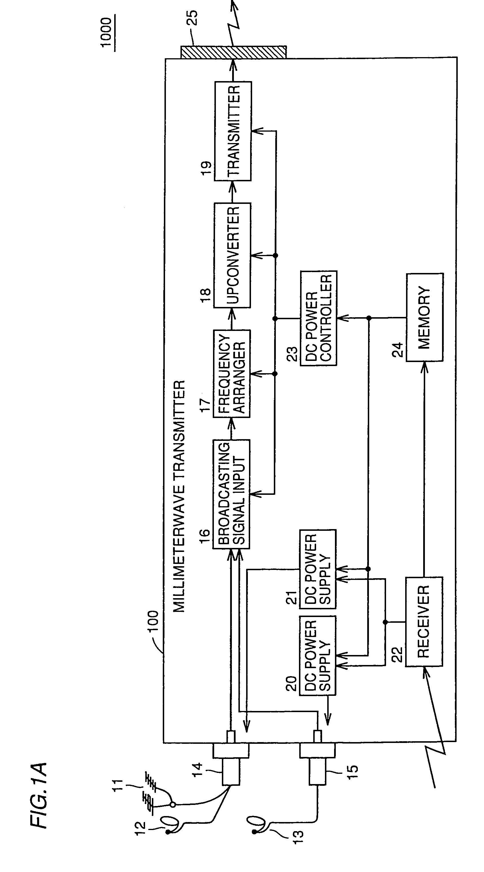
[0042]FIG. 1A is a block diagram showing the structure of a millimeter wave transmitter 100 forming a millimeter wave communication system 1000 according to a first embodiment of the present invention.

[0043]The millimeter wave transmitter 100 includes a VHF / UHV antenna 11, a BS antenna 12, a CS antenna 13, a connector 14, another connector 15, a broadcasting signal input 16, a frequency arranger 17, an up converter 18, a transmitter 19, a DC power supply 20, another DC power supply 21, a receiver 22, a DC power controller 23, a memory 24 and a millimeter wave antenna 25.

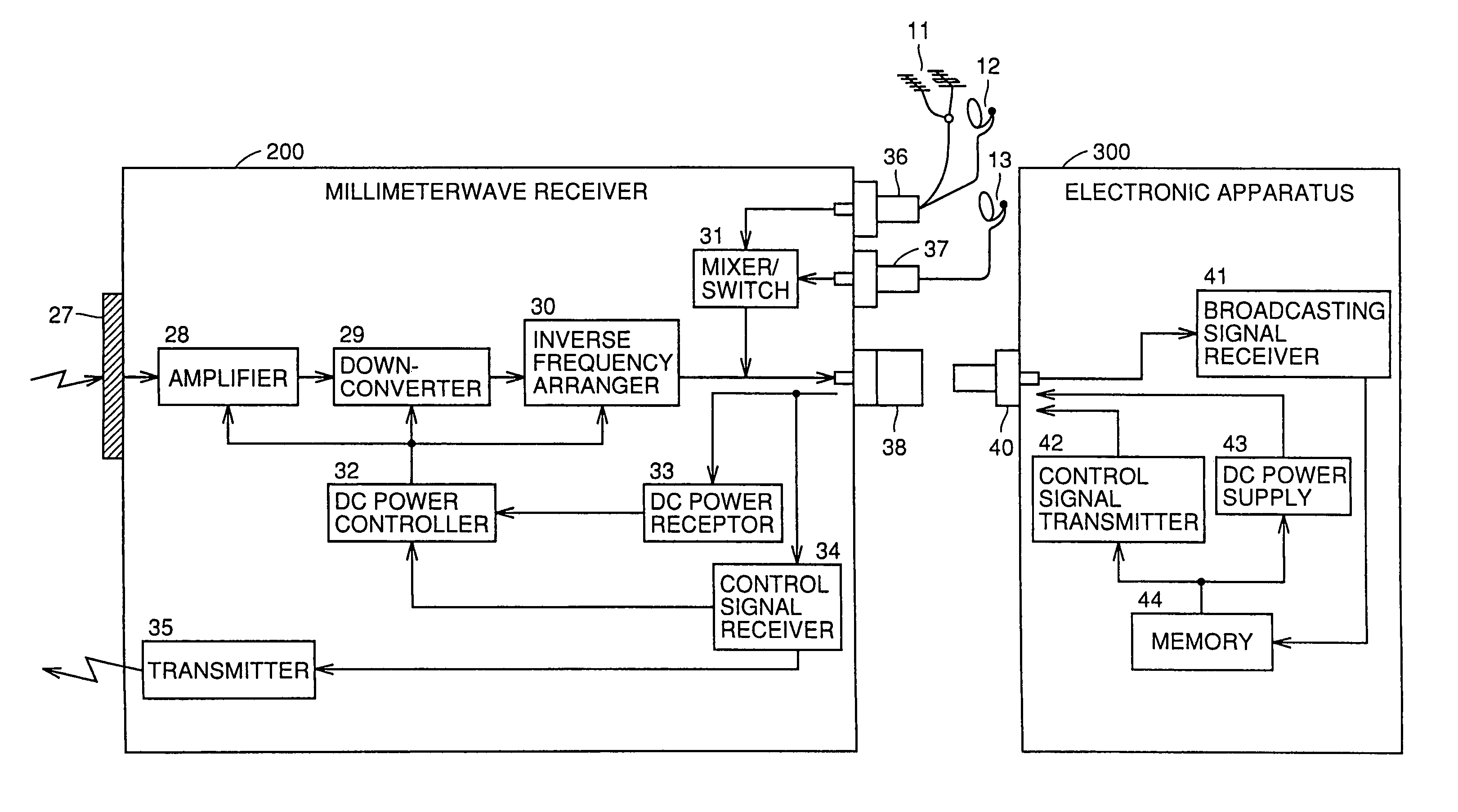
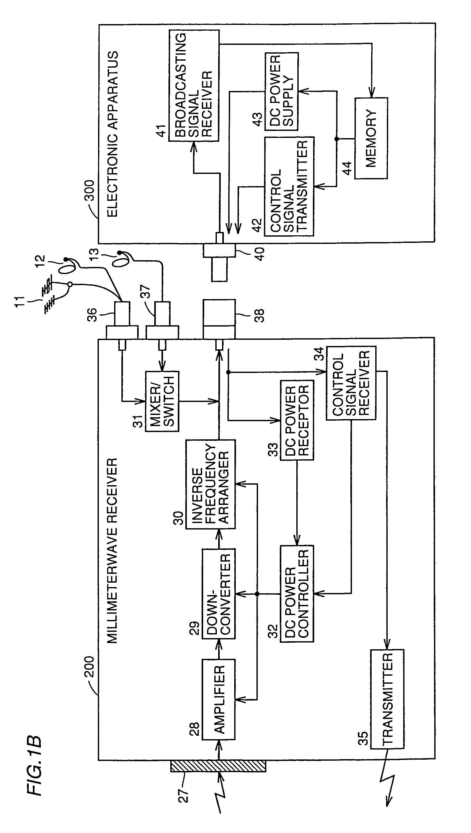
[0044]FIG. 1B is a block diagram showing the structure of a millimeter wave receiver 200 and an electronic apparatus 300 forming a millimeter wave communication system 1000 according to a first embodiment of the present invention.

[0045]Referring to FIG. 1B, a millimeter wave receiver 200 includes a millimeter wave antenna 27, an amplifier 28, a down converter 29, an inverse frequency arranger 30, a mixer / switch 31, a...

second embodiment

[0115]FIGS. 14A and 14B are block diagrams showing the structure of a millimeter wave transmission system 2000 having a repeater 500 according to a second embodiment of the present invention.

[0116]FIG. 14A shows the structure of the repeater 500 included in the millimeter wave transmission system 2000. FIG. 14B shows the structure of a millimeter wave transmitter 120 included in the millimeter wave transmission system 2000. The millimeter wave transmitter 120, employed in combination with the repeater 500, has a structure corresponding to the repeater 500.

[0117]The structures of a millimeter wave receiver and an electronic apparatus corresponding to the millimeter wave transmission system 2000 are identical to those described with reference to the first embodiment and hence redundant description is not repeated. In other words, the millimeter wave communication system shown in the first embodiment can be formed by combining any of the millimeter wave receivers 200 to 240 and the ele...

third embodiment

[0127]FIG. 15 is a block diagram showing the structure of an electronic apparatus 310 having a millimeter wave receiving function according to a third embodiment of the present invention.

[0128]Referring to FIG. 15, the electronic apparatus 310 includes a millimeter wave antenna 27, an amplifier 28, a down converter 29, an inverse frequency arranger 30, a mixer / switch 31, a DC power controller 32, a transmitter 35, a connector 40 and a broadcasting signal receiver 41.

[0129]Signals from general antennas for terrestrial broadcasting, BS broadcasting and CS broadcasting are input from the connector 40, so that the electronic apparatus 310 storing a millimeter wave receiver is connected to the general antennas without through the millimeter wave receiver. Millimeter waves transmitted from the millimeter wave transmitter are received by the millimeter wave antenna 27 and amplified by the amplifier 28. The amplified receiving signals are down-converted by the down converter 29 and finally ...


PUM


Abstract

In order to receive satellite broadcasting (BS and CS) and terrestrial broadcasting (VHF and UHF), complicated wiring is required in a personal residence for transmitting broadcasting signals to a plurality of TV receivers while new distributors must be additionally set for installing additional TV receivers in a condominium previously provided with distributors limiting the number of settable TV receivers. The inventive millimeter wave communication system forms power supply paths by simply connecting a BS/CS antenna with a millimeter wave transmitter and connecting an electronic apparatus such as a TV receiver with a millimeter wave receiver through connectors or the like while transmitting/receiving broadcasting signals by millimeter wave radio communication without employing wires such as coaxial cables indoors.

Description

BACKGROUND OF THE INVENTION[0001]1. Field of the Invention[0002]The present invention relates to a millimeter wave transmitter, a millimeter wave receiver, a millimeter wave communication system, a repeater and an electronic apparatus for radio-transmitting a plurality of broadcasting waves of terrestrial broadcasting such as VHF / UHF broadcasting or satellite broadcasting such as BS (broadcasting satellite) broadcasting or CS (communication satellite) broadcasting in millimeter waves indoors.[0003]2. Description of the Background Art[0004]At present, broadcasting is implemented over a plurality of radio bands for terrestrial broadcasting (UHF and VHF) and satellite broadcasting (BS and CS).[0005]FIG. 16 illustrates the structure of a conventional TV broadcasting receiving system 800 in a personal residence.[0006]The TV broadcasting receiving system 800 receives satellite broadcasting signals of the 12 GHz band in a BS antenna 71 and a CS antenna 72 respectively. Low-noise converters...

Claims


Application Information

Patent Timeline
IPC IPC(8): H04N7/18H04N7/10H04B1/08H04B1/18H04B1/26H04B1/38H04B7/155H04B7/24H04H20/00H04H20/06H04N5/00H04N7/16H04N7/20H04N21/434H04N21/438H04W4/04H04W16/26
CPCH04H20/02H04H20/06H04N7/20H04H20/61H04N5/63
Inventor SUEMATSU, EIJIAOKI, TAMOTSUOGATA, YASUOSUZUKI, MASAMINAKAMURA, TOSHIOSEKI, YOSHINORI
Owner SHARP KK
Why Eureka
Try Eureka