
Dental mirror

a technology for dental mirrors and mirrors, applied in the field of dental mirrors, can solve the problems of affecting the vision of the operator, and affecting the treatment effect of patients, and is rarely suitable for handling appreciable volumes of liquids

Inactive Publication Date: 2006-04-04
TSIMERMAN EFRAIM +1
View PDF20 Cites 27 Cited by
  • Summary
  • Abstract
  • Description
  • Claims
  • Application Information

AI Technical Summary

Benefits of technology

[0016]In accordance with another aspect of the invention, the light source or sources may be one or more LED's.

Problems solved by technology

Debris, which may be either solid or liquid, eventually blocks the operator's vision and forces the operator to frequently clean the mirror surface either by wiping it off or by having another person assisting during the medical procedures, apply fluid onto the mirror.
Both of these procedures are frustrating and objectional to the medical professional.
In other cases, surfactants and anti-fogging solutions have been applied over the surface of the mirror but these are seldom suitable for handling appreciable volumes of liquids such as cooling water associated with a dental hand piece.
The heat and / or chemicals involved in disinfection tend to shorten the life of the mechanical features included for debris removal.
Additionally, the reflective surface is subject to abrasion from the constant deposition and removal of debris and accordingly, the useful life of reflective surface is relatively short in most cases, even shorter than the mechanical components referred to above.
A second problem which is often associated with the use of such mirrors within cavities, arises from the need to direct light to a desired area within the cavity.
The problem may be exacerbated as the mirror is often deployed at different angles depending upon whether the dentist is working on the upper dental arch or the lower dental arch and whether the dentist is working on the patient's right side or left side of the oral cavity.

Method used


Image

  • Dental mirror
  • Dental mirror
  • Dental mirror

Examples


Embodiment Construction

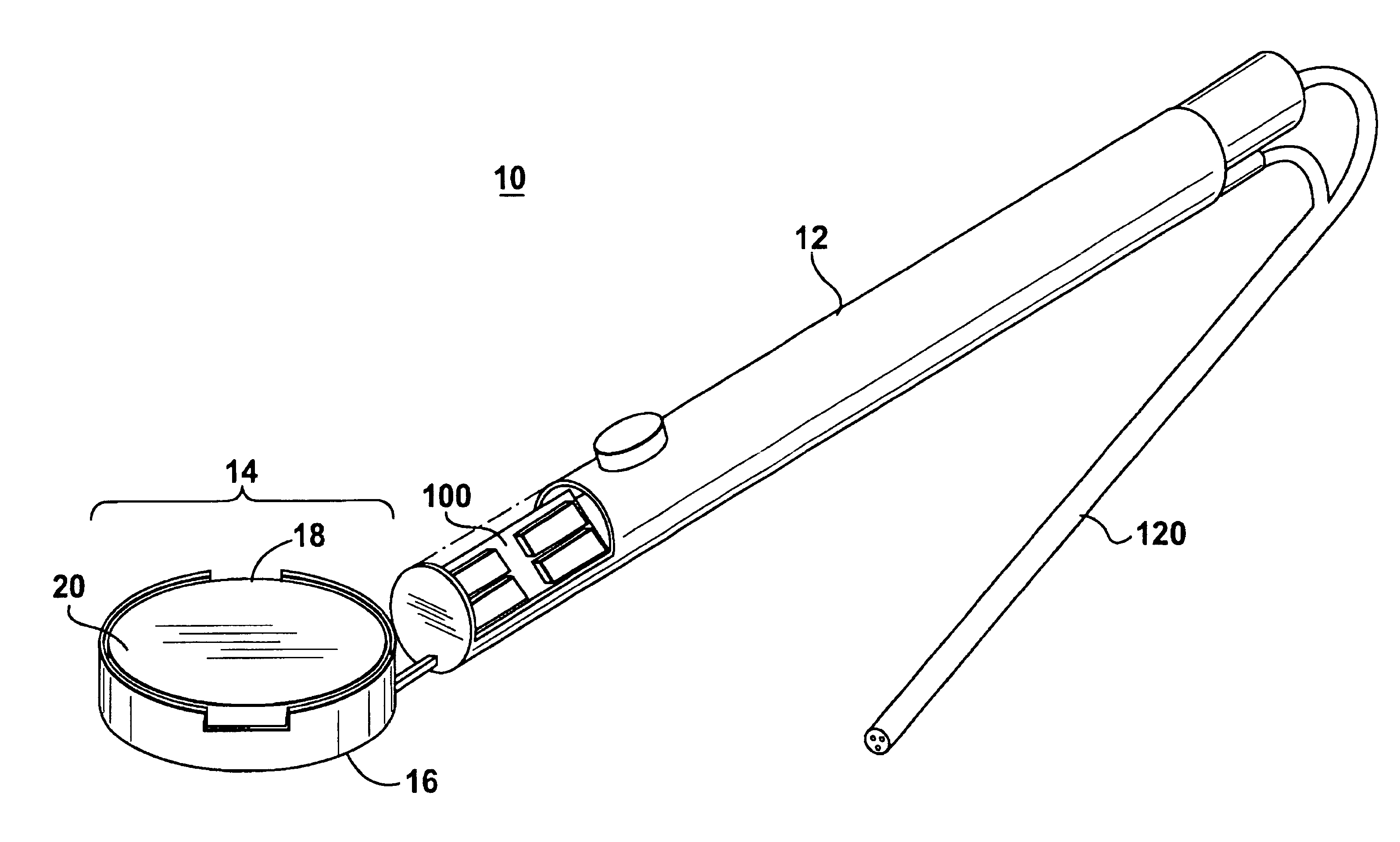
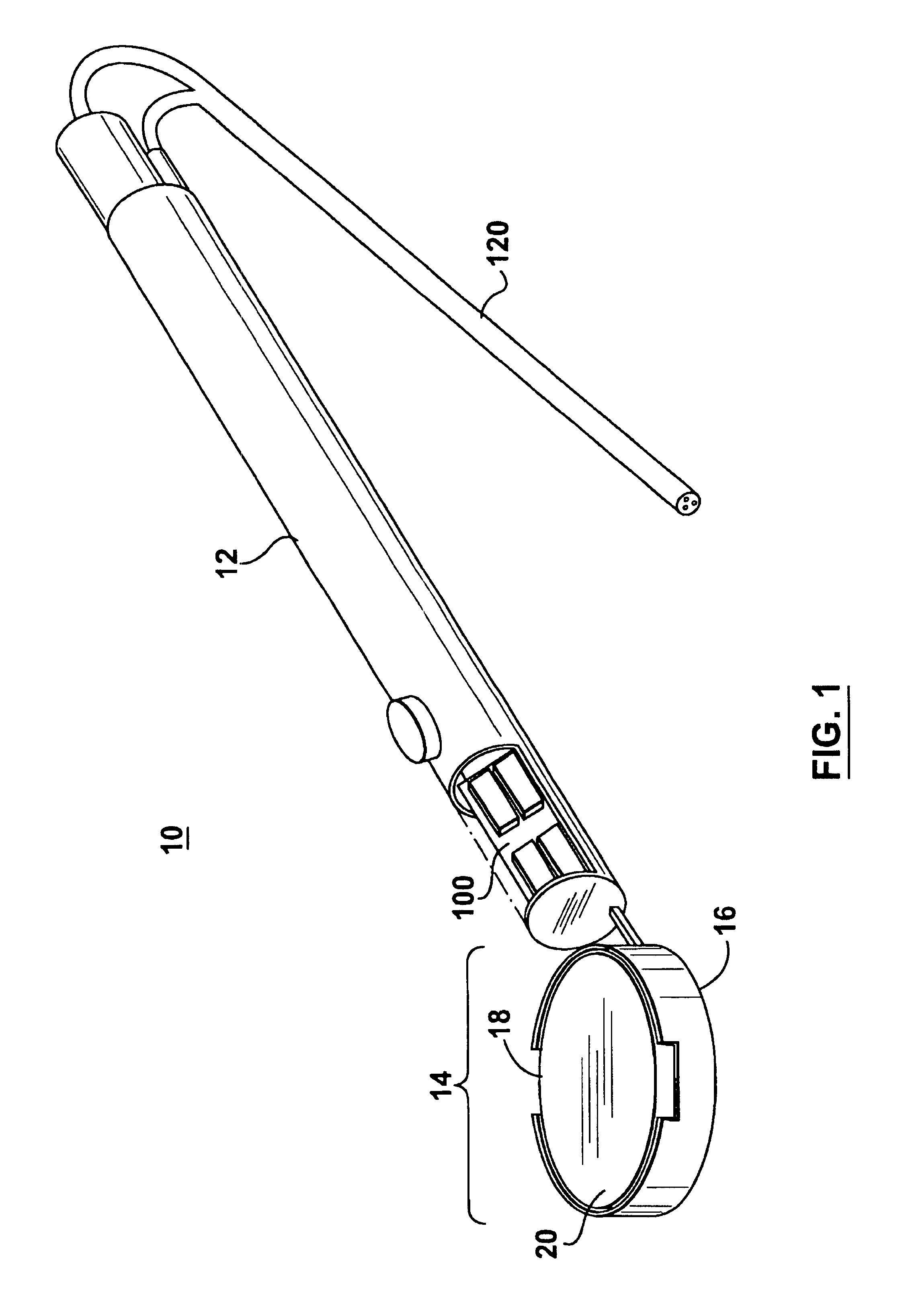
[0038]A first embodiment in accordance with the invention is illustrated in FIG. 1. The embodiment illustrated in this figure is a dental mirror assembly for use by dentists in performing typical dental procedures within a patient's oral cavity. The dental mirror assembly is illustrated generally at 10. The dental mirror assembly 10 includes a handle portion 12 and a head portion 14. The head portion 14 is attached to the handle portion structurally to enable the dentist to maneuver the head portion by manipulating the handle portion 12. In addition, the structural connection between the head portion 14 and the handle portion 12 may include conduits for communicating electrical wires and in addition fluids, all as more fully explained below.

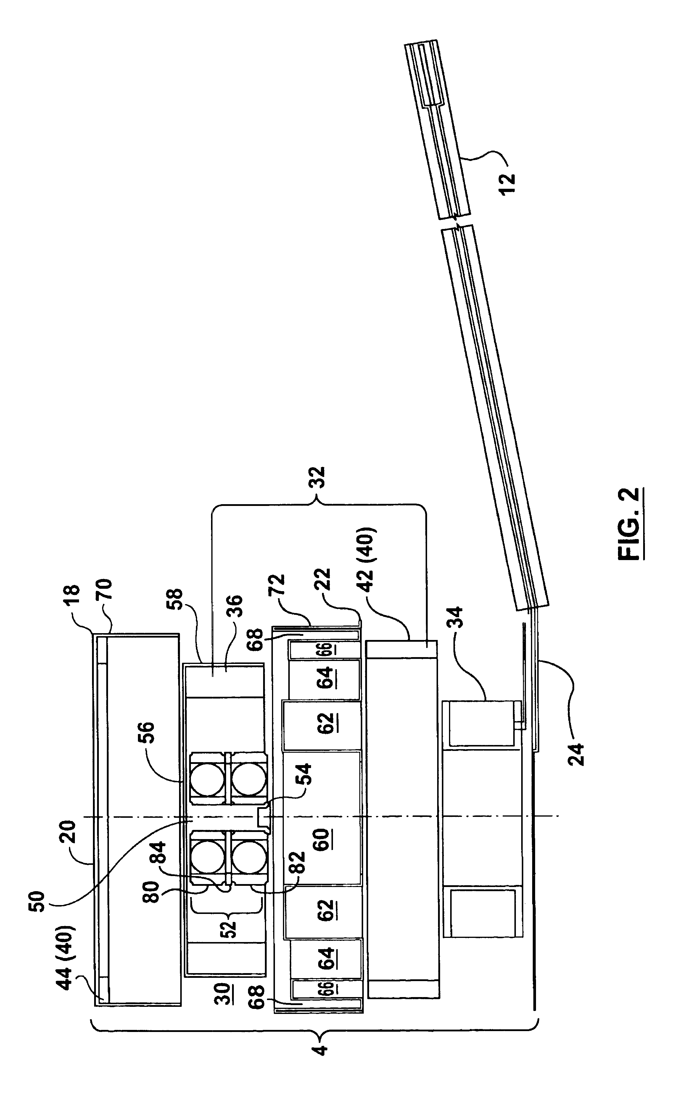
[0039]As illustrated in FIGS. 1 and 2, the head portion 14 includes a housing 16 and a secondary member 18. The secondary member 18 includes a reflective surface 20. The housing 16 comprises an upper shell 22 and a lower shell 24. The housing 16 ...


PUM


Abstract

The invention relates to mirrors for use in confined spaces which are subject to being covered by fluids and debris, principally dental mirrors, for use by dentists and similar medical professionals. The mirror assembly includes a head portion and a handle portion. The head portion includes a housing with a rotor assembly and a rotor drive means. In accordance with the invention, a secondary member has a reflective surface. The mirror assembly includes attachment means for removably attaching the secondary member with respect to the rotor assembly so that the reflective surface can be replaced when degraded. In use, the rotor drive means spins the rotor assembly and with it the secondary member to remove fluids and debris that may fall on the reflective surface so that vision when using the reflective surface is not impaired by such fluids or debris. Advantageously the attachment means include magnetic components although mechanical attachment means may also be used. In a preferred embodiment, the handle portion includes a light source which may be moved between first and second positions for lighting the work zone of the mirror selectively as desired.

Description

FIELD OF THE INVENTION[0001]This invention relates to mirrors used for examination of cavities such as a surgical mirror or a dental mirror having a reflective surface supported on a handle for viewing desired work sites within the cavity.BACKGROUND OF THE INVENTION[0002]During dental procedures it is common for dentists or other medical professionals working in the oral cavity to make use of a mirror. The mirror is usually mounted on a handle with the plane of the mirror being at an angle to the handle. The mirror is used at the same time as other dental instruments, to facilitate viewing or illumination of the work site.[0003]While conducting appropriate medical procedures at a work site, it is often the case that various substances may fall on the reflective surface of the mirror. This may include bodily fluids originating in the cavity being worked on, cooling fluids originating from a dental hand piece or other medical instrument or other debris which maybe generated at the wor...

Claims


Application Information

Patent Timeline
IPC IPC(8): B60Q3/04A61B1/247
CPCA61B1/00096A61B1/247A61B1/00101Y10S362/80
Inventor TSIMERMAN, EFRAIMCHOUSTER, EMIL
Owner TSIMERMAN EFRAIM
Learn More