Fan assembly mechanism

Inactive Publication Date: 2006-04-04
INVENTEC CORP
View PDF1 Cites 19 Cited by
  • Summary
  • Abstract
  • Description
  • Claims
  • Application Information

AI Technical Summary

Benefits of technology

[0014]Consequently, the fan assembly mechanism formed with the fastening members and the elastic fastener according to the invention can adequately resolve the technique problems occurring in the

Problems solved by technology

Therefore, to achieve the objective of reducing operating temperature, a fan member must be installed in a computer system or an electronic device to circulate air and radiate heat; otherwise accumulated heat inside the casing of a computer system or an electronic device during operation will raise the temperature and shorten the life-span of computer chips or other electrical components.
Moreover, serious damage may be caused by burnout of computer chips or electric circuits; thereby a computer or an electronic device can immediately fail to operate thereafter.
The motor generates power from electric current, thereby revo

Method used


Image

  • Fan assembly mechanism
  • Fan assembly mechanism
  • Fan assembly mechanism

Examples


Embodiment Construction

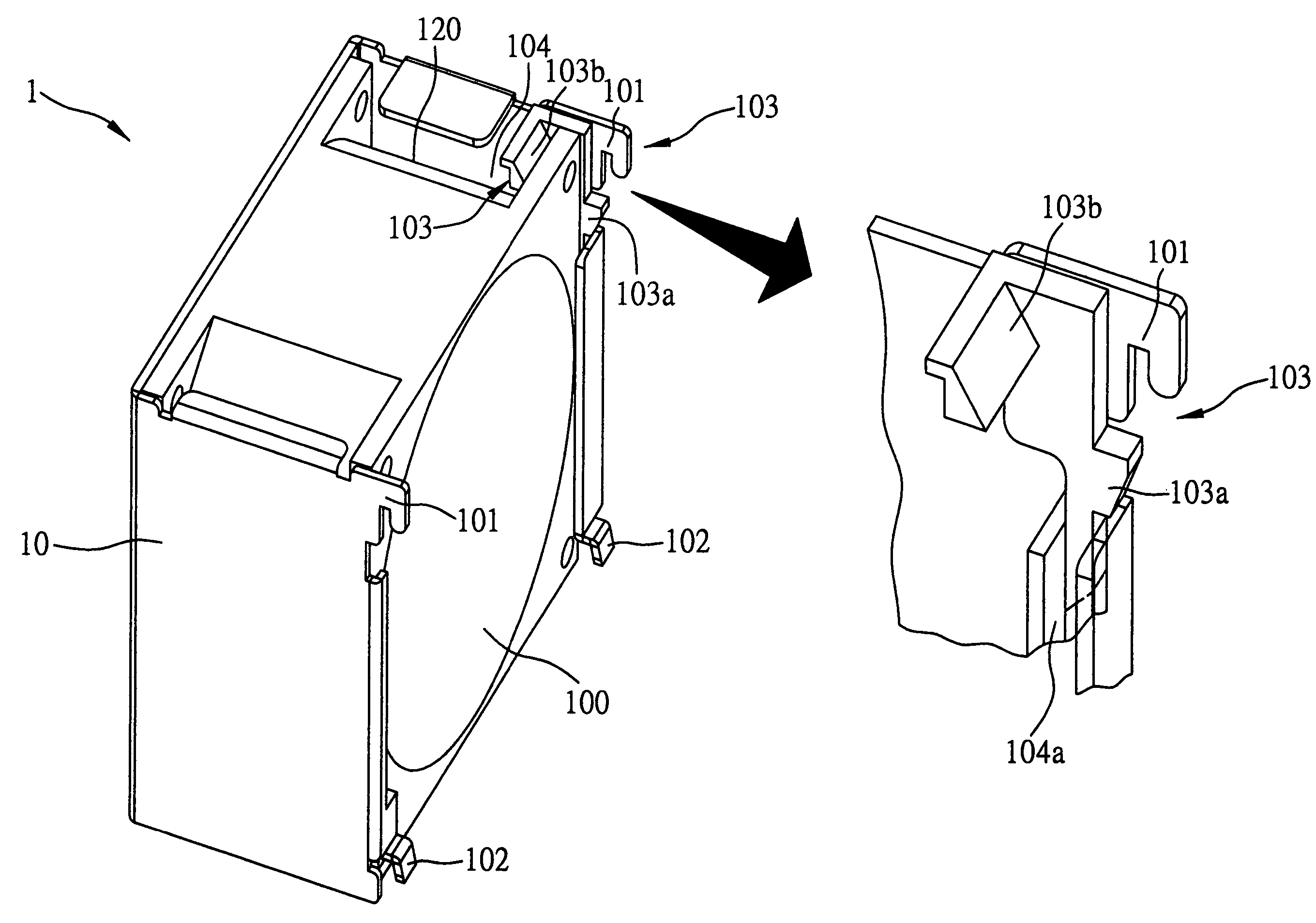
[0022]A preferred embodiment of the present invention is shown in FIG. 3 wherein a fan assembly mechanism 1 comprises a fan member 10 formed with an interior space 120 enabling fan blades and a motor (not shown) to be installed for performing air circulation and heat radiation. The fan member 10 has a flat mounting surface 100 thereof affixed on a wall mounting surface 106 of the casing of an electronic device 105. The flat mounting surface 100 has four corners thereof respectively formed with fasteners, which are integrally formed with the fan member 10 and include first fastening members 101 positioned on the upper corners of the fan member 10 and corresponding second fastenings 102 positioned on the lower corners. The first fastening members 101 protrude outward and then downward from the flat mounting surface 100 forming recessed portions; while the second fastening members 102 protrude downward from the flat mounting surface 100 forming hook-like portions.

[0023]In addition, the...


PUM


Abstract

A fan assembly mechanism is disclosed for mounting a fan member on a wall mounting surface of a casing, including the fan member having a flat mounting surface and a space for receiving at least one fan; at least one fastening member formed on the flat mounting surface; and an elastic fastener having its one side fixed on the fan member and at least one latching portion protruded out of the flat mounting surface. The fan assembly mechanism allows the fastening member to engage a corresponding hole on the wall mounting surface of the casing, and the latching portion to engage another hole on the casing, so as to assemble the fan member to the casing.

Description

[0001]This Nonprovisional application claims priority under 35 U.S.C. § 119(a) on Patent Application No(s). 092204993 filed in TAIWAN on Mar. 31, 2003, the entire contents of which are hereby incorporated by reference.FIELD OF THE INVENTION[0002]The invention relates to fan assembly mechanisms, and particularly to an improved assembly mechanism enabling fan members to be easily mounted on and dismantled from the casing of an electronic device.BACKGROUND OF THE INVENTION[0003]Generally, a computer system or an electronic device has a variety of IC parts installed inside the casing thereof, such as a CPU, a power supply, and a circuit board whereon various electrical components are mounted. A great quantity of heat is generated during computer operation when electric current flows through electric circuits, which are densely placed in chips or on a circuit board. Therefore, to achieve the objective of reducing operating temperature, a fan member must be installed in a computer system ...

Claims


Application Information

Patent Timeline
IPC IPC(8): F04B17/03F04D29/60
CPCF04D29/602
Inventor CHANG, LIN-WEI
Owner INVENTEC CORP
Why Eureka
Try Eureka