
Sectional rail system as base for a plate covering

Active Publication Date: 2011-03-10
ZAK IT SYST
View PDF11 Cites 2 Cited by
  • Summary
  • Abstract
  • Description
  • Claims
  • Application Information

AI Technical Summary

Benefits of technology

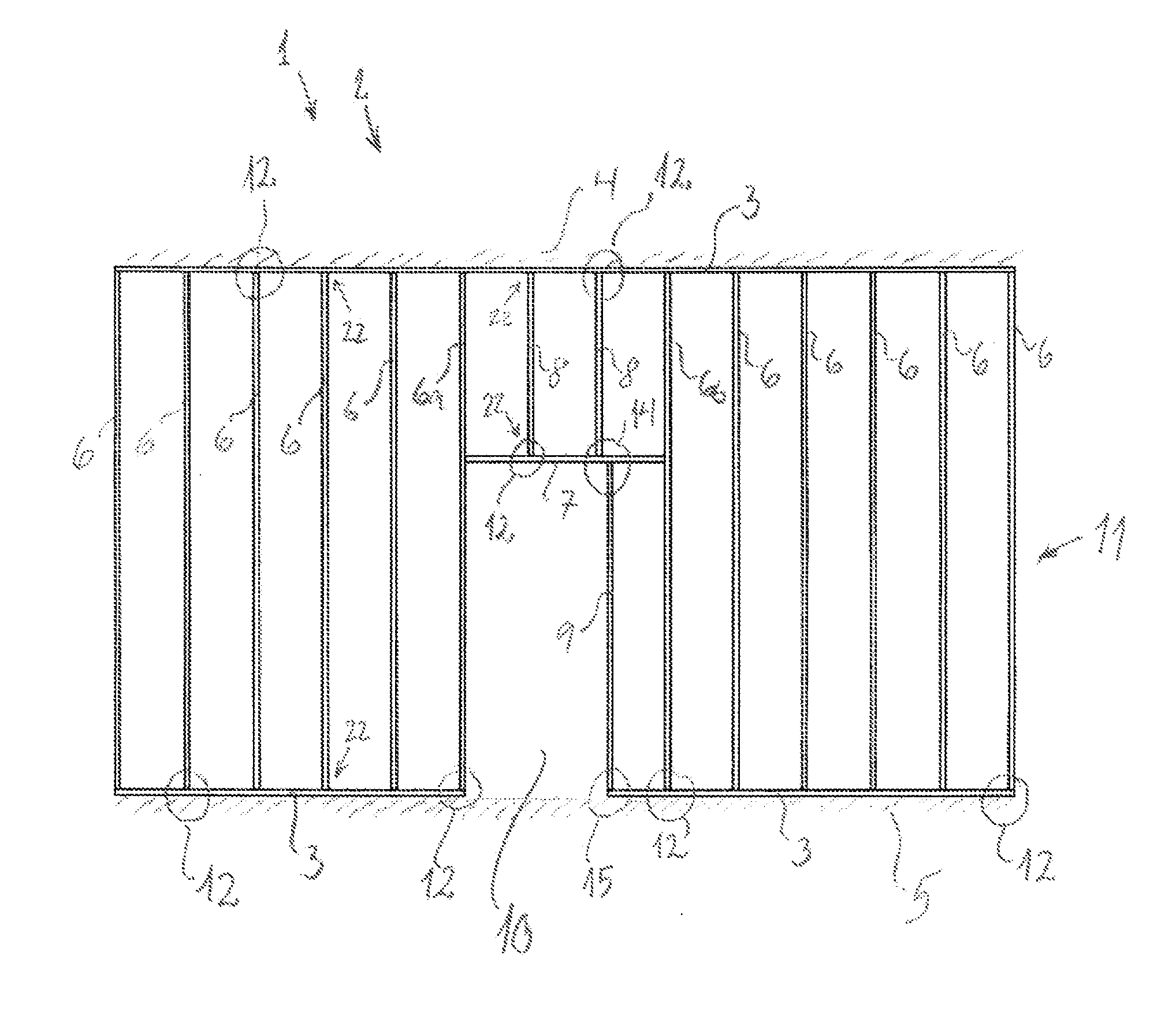
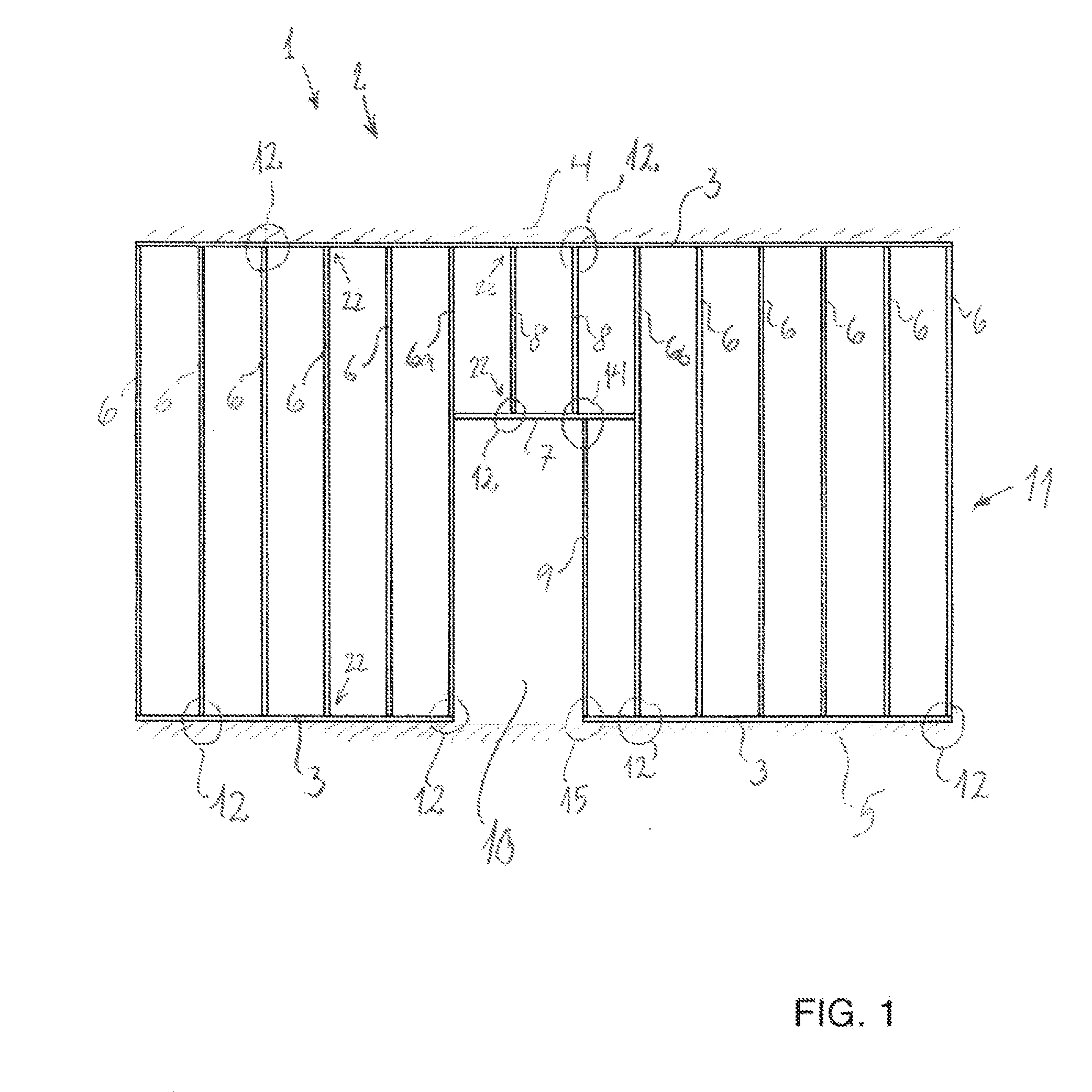
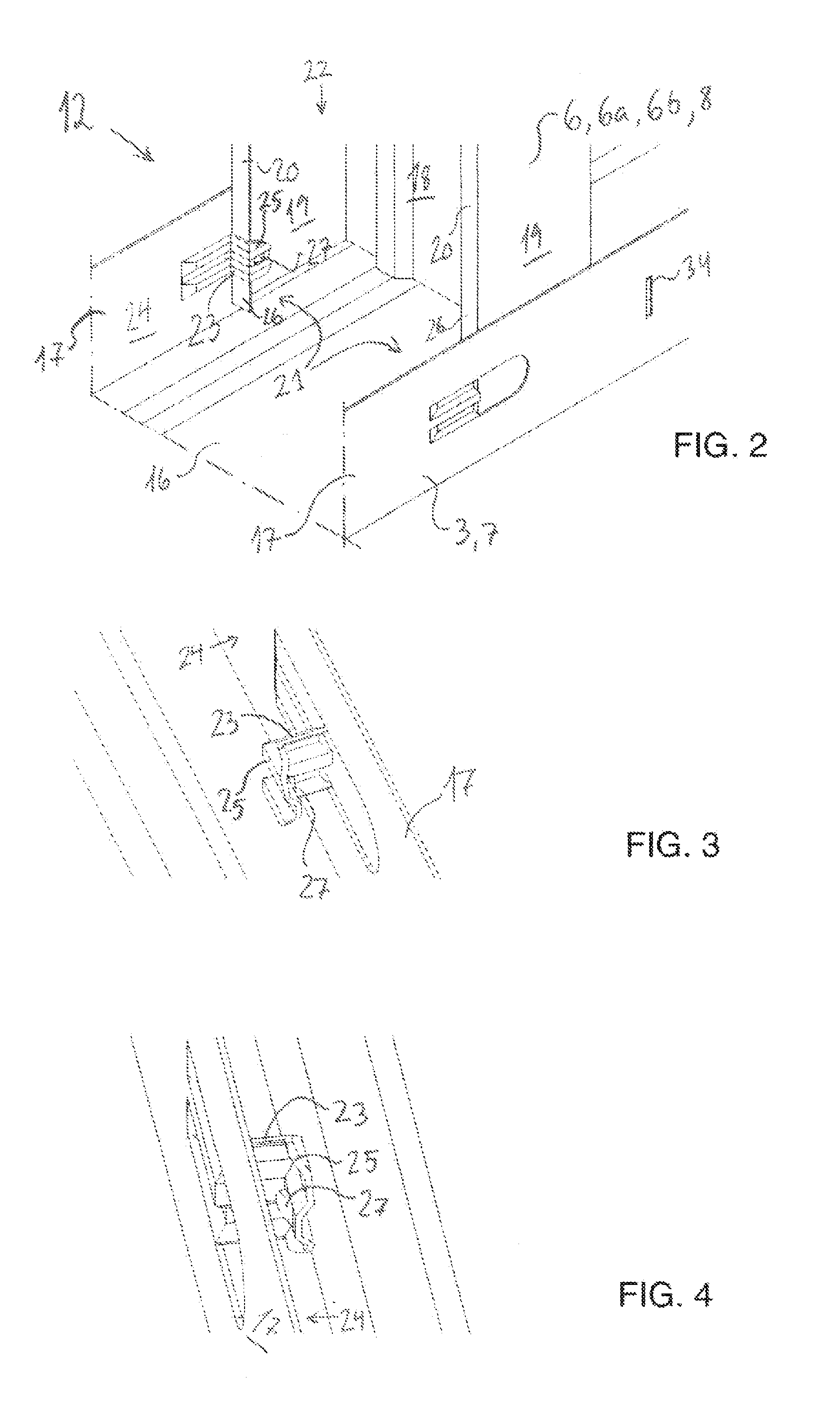
[0028]A sectional rail system which is designed with the prior art outer rails with U-shaped cross-section and intermediate rails with C-shaped cross-section as described above, and which has the peculiar features mentioned in claim 1 with one or more stop pins with associated support flange, has the advantage that the screw web at the lower end part of the intermediate rail which during screwing on of the plate cover by the prior art sectional systems does to have sufficient support, this screw web is now supported via a support of the inwardly projecting reinforcement web where this support is constituted by the support flange on the stop pin.
[0029]Hereby is achieved that by screwing on plate covering close to the edge part of the intermediate rail, it is avoided that the screw web and the associated reinforcement web “capsize”. The support flange ensures a sufficient retention for the force applied to the screw web during screwing, e.g. with a self-tapping or self-cutting screw. The support flange thus provides for the screw web remaining in position during the screwing such that the screw get sufficient hold of the base, thereby becoming mounted correctly.
[0030]At the same time, by disposing the stop pin close the screw webs of the outer rail it is possible the achieve a solution where the length of the intermediate rails may vary within an appropriate tolerance range corresponding to a usual length tolerance when adaptation of sectional length occurs on a construction site.
[0035]In a further preferred embodiment, each support flange on each stop pin may be provided with lock pin. It is thus ensured that the intermediate rail is retained close to both screw webs of the outer rail, whereby a force action of a typical size attacking the intermediate rail, irrespective of the acting direction of the force, may be transmitted from the intermediate rail to the outer rail, and thereby be absorbed in the surrounding structure without giving rise to deformation.
[0039]In a further preferred embodiment, each of the intermediate rails may be provided with a number of cutouts that correspond to the position of the fastening means of a lintel rail and spaced apart from any of the ends of the intermediate rail, and against the sectional back of the intermediate rail and against the reinforcement flanges of the intermediate rail. Thereby, all intermediate rails can be made as identical standard sections as each intermediate rail may be equipped with the option of fastening the lintel rail in a tool-free way in the intermediate rail. It is thus not required to plan disposition of the specially designed intermediate rails in beforehand in the vicinity of door or window aperture, making the construction work easier and reducing the risk of time-consuming errors.

Problems solved by technology

There are the following disadvantages by this prior art:The modular dimensions between the intermediate rails may easily deviate, whereby the plaster board cannot be screwed on the intermediate rails with the required exact dimensions from screws to plate edge.The fixing by the fixing tongs frequently cannot stand when the workmen press the insulation into position.When screwing the plaster boards on, it is often difficult for a self-tapping screw to get hold of the screw webs at the end parts of the intermediate rails.
This is due to the fact that the aforementioned fixing cannot secure the screw web of the intermediate rail to the required extent.
Particularly around doors where dynamic action on the plate covering may occur regularly, this can result in that the plate covering of the wall works loose, thereby putting greater demands on maintenance.
This depreciation of quality is unwanted in modern building construction.The rail assembly is time-consuming as, for example, 8.88 rail joints have to be made per meter of wall when the intermediate rail spacing is 450 mm.
Thereby it is possible to click the intermediate rails securely into position without measuring.Since the intermediate rails are to be displaced perpendicularly into both outer rails, it is necessary to assemble the entire sectional rail system at a place with ample space around for subsequently erecting the sectional rail system (the wall) in one piece and securing it at the place of building-in.Moreover, there is therefore to be made intermediate rails that fit the given ceiling height since shortening at the mounting site cannot be effected as the possibility of rail assembly by clicking together is rendered impossible if the intermediate rails are shortened.The system is not flexible as intermediate rails have to be made for any ceiling height that may occur in a given building project, requiring substantial resources for planning the sectional rail system.The lateral flanges on the intermediate rails are not kept firmly in against the lateral flanges on the bottom and top rails.
The intermediate rails may hereby be displaced and the screw may have difficulty in getting hold, to the detriment of the quality of the work performed.
The drawbacks of this prior art is:There is required a very exact shortening of the intermediate rails as even small deviations of the length of the intermediate rails can entail that some of the intermediate rails will slide out of the locking pins.
The cutting tools used by the workmen for shortening frequently do not have the required precision.In practice, it will imply requirements to factory made intermediate rails and putting the outer rails on chocks, implying great demands on both construction site logistics, planning and mounting work.The lateral flanges on the intermediate rails are not kept firmly in towards the lateral flanges on the bottom and top rails at the rail joint.
The intermediate rails may hereby be displaced and the screws may have difficulty in getting hold, to the detriment of quality.
Concerning establishing door and window apertures, this work is tedious by all prior art sectional rail systems, why it is left to the building worker's creativity to provide the wanted door and window apertures.
A unnecessary use of material is thereby produced at the establishing of a door and window apertures in the prior art systems.
This is a cumbersome and time-consuming work that reduces the efficiency in the building process.
Insulation batts, which have standard dimensions, thus have to be adapted by cutting in all fields around the door and window apertures, which is a relatively time-consuming process.
In addition, in modern construction there are great demands to the quality and productivity in performing the work.

Method used


Image

  • Sectional rail system as base for a plate covering
  • Sectional rail system as base for a plate covering
  • Sectional rail system as base for a plate covering

Examples


Embodiment Construction

[0024]According to the present invention, this object is achieved by a sectional rail system of the type mentioned in the introduction, which is peculiar in that each of the retention means of the outer rail includes at least one stop pin which is disposed close to the inner side of the screw web of an outer rail, preferably two stop pins disposed opposite each other close to the inner side of the screw webs of the outer rail, where each stop pin furthermore is provided with a support flange for supporting an end part of the reinforcement web of the intermediate rail. The fastening means of the outer rail may thus include one, two or more stop pins, and one or more resilient lock pins.

[0025]A stop pin has the purpose of forming a stop for the end part of an intermediate rail. This means that it is a stop pin as soon as the U-shaped outer section is supplied with any kind of device preventing the movement of the intermediate rail in the entire free space provided between the planes c...


PUM


Abstract

The present invention concerns a sectional rail system which is constructed with the known outer rails with U-shaped cross-section and intermediate rails with C-shaped cross-section, and which is peculiar in that each of the retention means of the outer rail includes at least one stop pin which is disposed close to the inner side of the screw web of an outer rail, preferably two stop pins disposed opposite each other close to the inner side of the screw webs of the outer rail, where each stop pin furthermore is provided with a support flange for supporting an end part of the reinforcement web of the intermediate rail. The fastening means of the outer rail may thus include one, two or more stop pins, and one or more resilient lock pins.Hereby may be achieved provision of a tool-free assembly method for the sectional rail system and that by screwing on plate covering close to the edge part of the intermediate rail, it is avoided that the screw web and the associated reinforcement web “capsize”.

Description

FIELD OF THE INVENTION[0001]The present invention concerns a sectional rail system for constructing a base for plate covering, where the sectional rail system includes at least two outer rails between which are provided at least two intermediate rails, where the outer rails have U-shaped cross-section, including a sectional back and two screw webs, where the intermediate rails have C-shaped cross-section, including a sectional back and two screw webs and two inwardly projecting reinforcement webs, where each outer rail has a retention means, preferably several retention means disposed with a spacing in longitudinal direction of the outer rail, where each of the intermediate rails are with two end parts, where each of the two end parts are fastened to a retention means of an outer rail, the retention means including at least one stop pin and at least one resilient lock pin, where the stop pin is provided with arresting means for the end part of an intermediate rail, where the lock pi...

Claims


Application Information

Patent Timeline
IPC IPC(8): E04C3/02E04C3/00
CPCE04B2/7457E04B2/767E04B2/765
Inventor DOLLERUP, NIELS
Owner ZAK IT SYST
Learn More