Magnetoelectric magnetic field sensor with longitudinally biased magnetostrictive layer

a magnetic field sensor and longitudinal bias technology, applied in the field of magnetic field sensors, can solve the problems of inability to achieve a sensitivity of 10 pt/hz in practice, high cost and power consumption, and the excess of superconducting quantum interference devices (squids)

Inactive Publication Date: 2006-04-04
VIRGINIA TECH INTPROP INC
View PDF3 Cites 39 Cited by
  • Summary
  • Abstract
  • Description
  • Claims
  • Application Information

AI Technical Summary

Benefits of technology

[0013]The magnetostrictive layer can be 1.5, 3, 4 5, 10 100 or more...

Problems solved by technology

Superconducting quantum interference devices (SQUIDs) exceed this sensitivity, but are very expensive and power-consumptive since they require cryogenic cooling.
Other sensors such as fiber optic magnetometers and fluxgate magnetometers are less expensive than SQUIDs, but in theory have a lower sensitivity on the order of 10 pT/√Hz that in practice has not been achieved.
Opt...

Method used


Image

  • Magnetoelectric magnetic field sensor with longitudinally biased magnetostrictive layer
  • Magnetoelectric magnetic field sensor with longitudinally biased magnetostrictive layer
  • Magnetoelectric magnetic field sensor with longitudinally biased magnetostrictive layer

Examples


Embodiment Construction

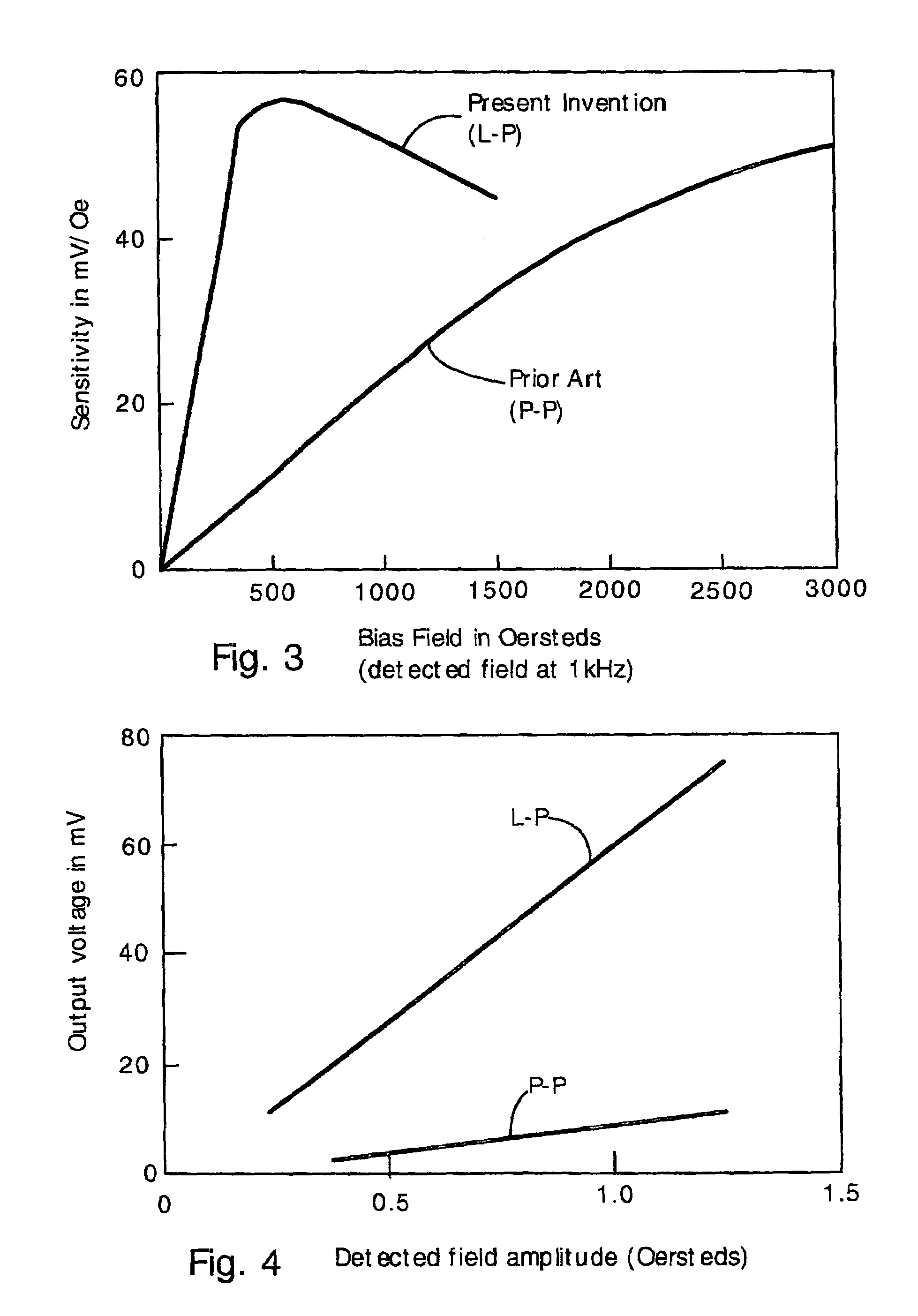
[0025]The present invention provides a magnetoelectric magnetic field sensor with extremely high sensitivity and low operating power requirements. The present sensor is sensitive enough to potentially provide long range (e.g. 0.01–1 km) sensing of vehicles and shorter range (<1 m) biomedical imaging (e.g. magnetoencephalographic imaging and magnetocardiac imaging).

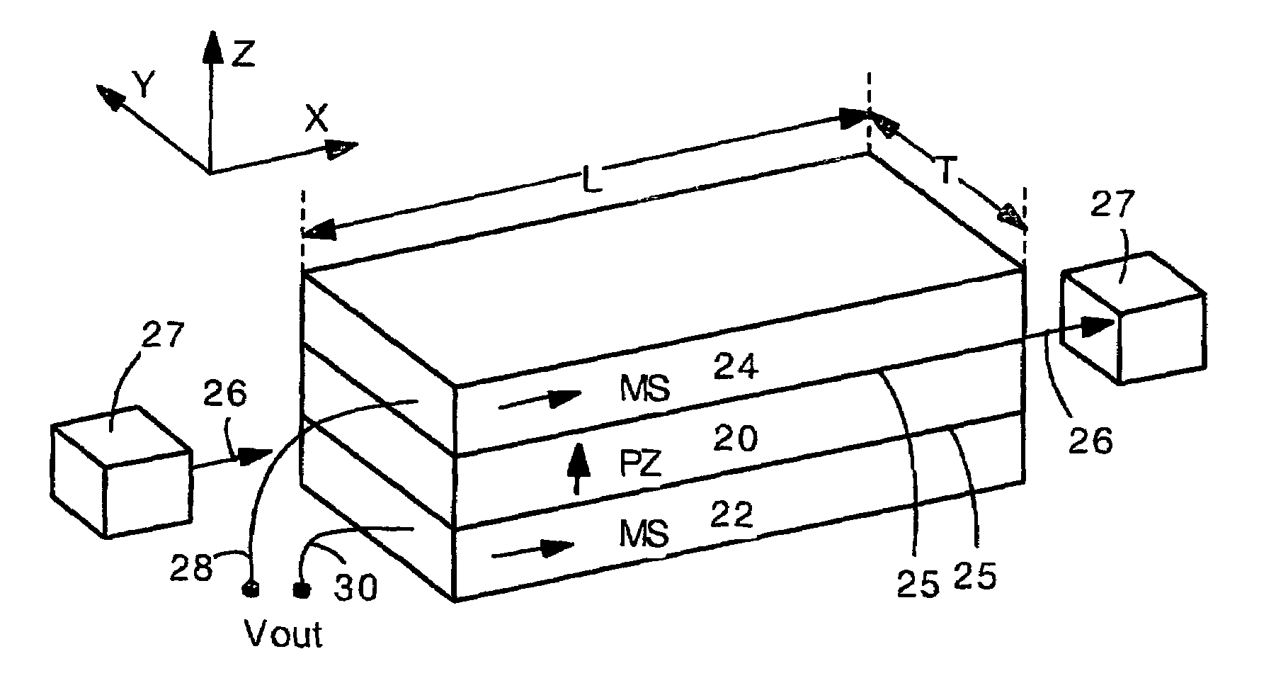
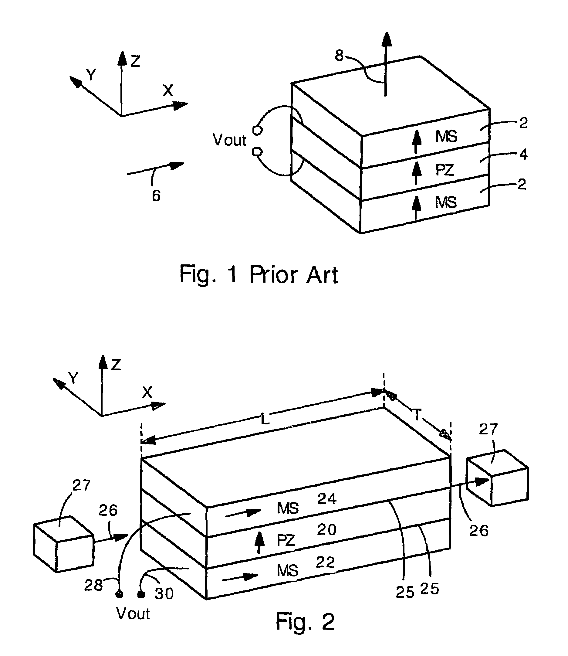
[0026]The present sensor has laminated magnetostrictive (MS) and piezoelectric (PZ) layers. An applied magnetic field strains the MS layer, which strains the PZ layer, thereby creating a detected output voltage. Significantly, the MS layer is magnetized by a bias field in a direction parallel to the plane of the MS layer (a longitudinal direction). Also, the magnetization layer has a length in the direction parallel with the magnetization that is greater than the transverse width. Additionally, the MS layers and PZ layers have an optimum thickness ratio for obtaining a maximum sensitivity. These three features provide exce...


PUM


Abstract

A magnetoelectric magnetic field sensor has one or more laminated magnetostrictive layers and piezoelectric layers. The magnetostrictive layers are magnetized by a bias magnetic field in a longitudinal, in-plane direction. The piezoelectric layers can be poled in the longitudinal direction or perpendicular direction. The longitudinal magnetization of the magnetostrictive layers provides greatly increased sensitivity at lower bias fields compared to other magnetoelectric sensors. Perpendicular poling of the piezoelectric layers tends to provide higher sensitivity at lower detection frequency (e.g. less than 1 Hz). Longitudinal poling tends to provide higher sensitivity at high detection frequency (e.g. above 10 Hz). Also included are embodiments having relative thicknesses for the magnetostrictive layers that are optimized for sensitivity. Equations are provided for calculating the best relative thickness for the magnetostrictive layer for maximum sensitivity.

Description

CROSS-REFERENCE TO RELATED APPLICATIONS[0001]This application claims priority to U.S. Provisional Application Ser. No. 60 / 419,102 filed Oct. 18, 2002.STATEMENT OF GOVERNMENT INTEREST[0002]This invention was made with government support under Grant Numbers 414167, 430955 and 430948 awarded by the Office of Naval Research. The Government has certain rights in the invention.FIELD OF THE INVENTION[0003]The present invention relates generally to magnetic field sensors. More specifically, the present invention relates to a magnetic field sensor having laminated piezoelectric and magnetostrictive layers in which the magnetostrictive layers are biased in a direction parallel with the layer plane.BACKGROUND OF THE INVENTION[0004]Magnetic sensors are used in many applications such as rotational and torque sensors for motors, proximity sensors for anomaly detection and the like. Magnetic sensors can also be used for biomedical imaging if made sensitive enough.[0005]Long-range proximity detecto...

Claims


Application Information

Patent Timeline
IPC IPC(8): G01R33/00G01R33/02
CPCG01R33/02H10N30/00
Inventor VIEHLAND, DWIGHTDONG, SHU-XIANGLI, JIE-FANG
Owner VIRGINIA TECH INTPROP INC
Why Eureka
Try Eureka