Apparatus and method for self-routing optical packet
a self-routing and optical packet technology, applied in multiplex communication, data switching networks, instruments, etc., can solve problems such as limiting transmission distance, affecting the transmission speed of optical packets, and inevitable problems such as degradation of transmitted waveforms
- Summary
- Abstract
- Description
- Claims
- Application Information
AI Technical Summary
Benefits of technology
Problems solved by technology
Method used
Image

Examples
first embodiment
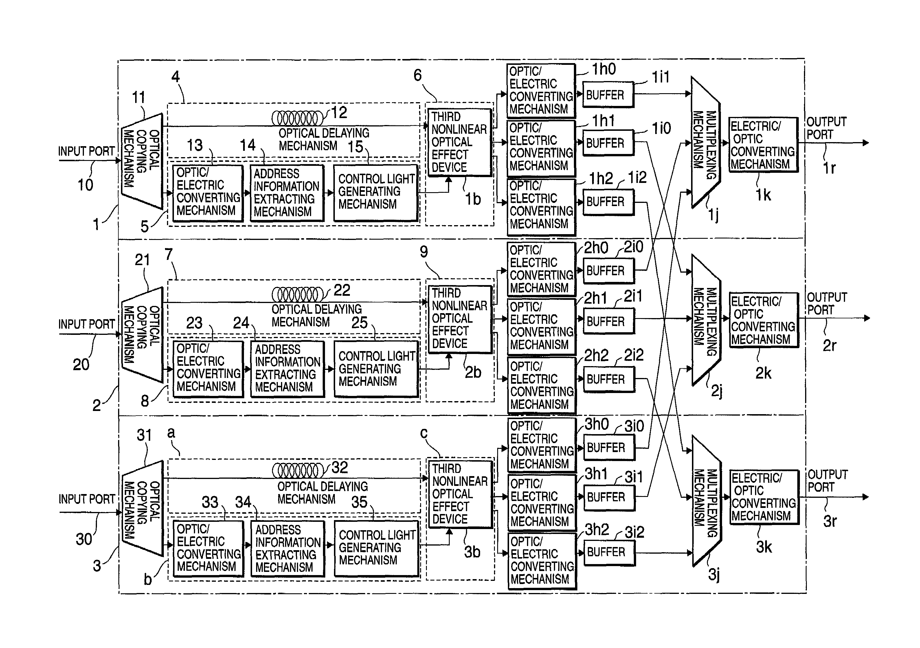
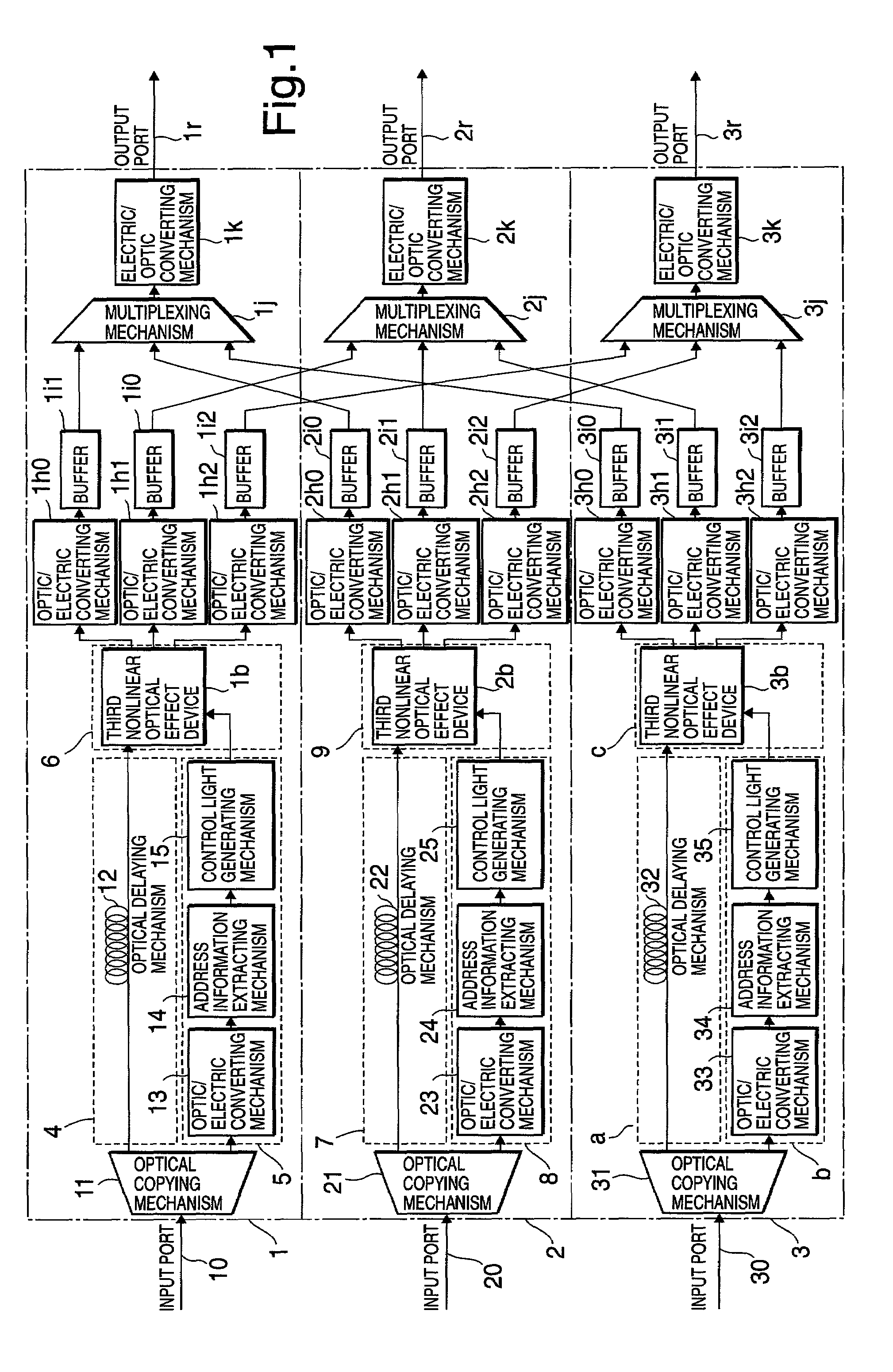
[0022]FIG. 1 shows a configuration of a self-routing apparatus of an optical packet according to the present invention. Hereinafter, by referring to FIG. 1, description is made of the configuration and an operation of the optical packet self-routing apparatus of the embodiment.
[0023]In the embodiment, the self-routing apparatus of the optical packet is composed of portions 1, 2 and 3.
[0024]The portion 1 includes an input port 10, an optical copying mechanism 11, a channel route 4, a control system route 5, a portion 6, optic / electric converting mechanisms 1h0 to 1h2, buffers 1i0 to 1i2, a multiplexing mechanism 1j, an electric / optic converting mechanism 1k, and an output port 1r. The channel route 4 has an optical delaying mechanism 12. The control system route 5 has an optic / electric converting mechanism 13, an address information extracting mechanism 14, and a control light generating mechanism 15. The portion 6 has a third nonlinear optical effect device 1b.
[0025]The portion 2 i...
second embodiment
[0070]FIG. 4 shows a configuration of a self-routing apparatus of an optical packet according to the present invention. Hereinafter, by referring to FIG. 4, description is made of the configuration and an operation of the optical packet self-routing apparatus of the embodiment.
[0071]In the embodiment, the self-routing apparatus of the optical packet is composed of portions d to j. The portion j includes portions 46, 49 and 4c.
[0072]The portion d includes an input port 10, an optical copying mechanism 11, a channel route 4, a control system route 5, and a wavelength multiplexing mechanism 6. The channel route 4 has an optical delaying mechanism 12. The control system route 5 has an optic / electric converting mechanism 13, an address information extracting mechanism 14, and a control light generating mechanism 15. The portions e and f are similar in configuration to the portion d.
[0073]The portion 46 includes interfaces 17 and if, transmission lines 19 and 1a, a wavelength demultiplex...
fourth embodiment
[0140]The removal of the limitations on the transmission distance on the electric signal, and the prevention of the phase deviation between the optical packet and the control light upon the entry to the third nonlinear optical effect device can also be achieved by using light parallel transmitting mechanisms 116, 118, 126, 128136 and 138 shown in FIG. 11. In the invention shown in FIG. 11, as such a light parallel transmitting mechanism, for example, a fiber array having optical transmission lines of equal lengths installed in parallel, or the like can be used. In addition, the wavelength multiplexing mechanisms 1e, 2e and 3e, and the wavelength demultiplexing mechanisms 1g, 2g and 3g shown in FIG. 4 can also be changed to light parallel transmitting mechanisms 11e, 12e, 13e, 11g, 12g and 13g shown in FIG. 11. Accordingly, by using the light parallel transmitting mechanisms lower in price than the wavelength demultiplexing / multiplexing mechanisms, it is possible to reduce costs of t...
PUM
| Property | Measurement | Unit |
|---|---|---|
| time | aaaaa | aaaaa |
| refractive index | aaaaa | aaaaa |
| wavelengths | aaaaa | aaaaa |
Abstract
Description
Claims
Application Information
 - R&D Engineer
- R&D Manager
- IP Professional
- Industry Leading Data Capabilities
- Powerful AI technology
- Patent DNA Extraction
Browse by: Latest US Patents, China's latest patents, Technical Efficacy Thesaurus, Application Domain, Technology Topic.
© 2024 PatSnap. All rights reserved.Legal|Privacy policy|Modern Slavery Act Transparency Statement|Sitemap