Vehicle component tamper detection system

a detection system and component technology, applied in the direction of burglar alarm mechanical actuation, anti-theft devices, instruments, etc., can solve the problems of tampering itself and impede visual confirmation, and achieve the effect of reducing the number of assembly steps, reducing layout limitations, and increasing layout flexibility

Inactive Publication Date: 2007-01-25
HONDA MOTOR CO LTD
View PDF20 Cites 45 Cited by
  • Summary
  • Abstract
  • Description
  • Claims
  • Application Information

AI Technical Summary

Benefits of technology

[0049] According to the vehicle component tamper detection system of the present invention as described above, employment of the wireless transmission method eliminates limitations in layout and increases layout flexibility. At the same time, this contributes to a decrease in the number of assembly steps and reductions in manufacturing costs. In addition, it is possible to provide the counter-measures that make it difficult to recognize the device from an exterior view.
[0050] By providing counter-measures that make it difficult to recognize the device from an exterior view, such as miniaturization of the device, it becomes even more difficult to spot the device, thus contributing to the prevention of the tampering.
[0051] Moreover, by attaching different types of identification chips to different vehicle components, respectively, it is possible to facilitate and ensure the detection of the tampering with external wireless recognition only, at a position distant from the automobile to be detected.

Problems solved by technology

Accordingly, it is possible to impede visual confirmation of the RFID, and thereby making the tampering itself difficult.

Method used


Image

  • Vehicle component tamper detection system
  • Vehicle component tamper detection system
  • Vehicle component tamper detection system

Examples


Embodiment Construction

[0062] The following describes the preferred embodiments of the present invention with reference to the drawings.

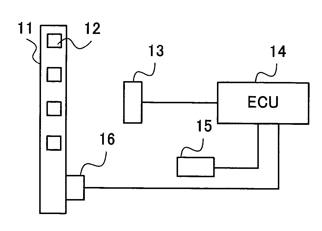
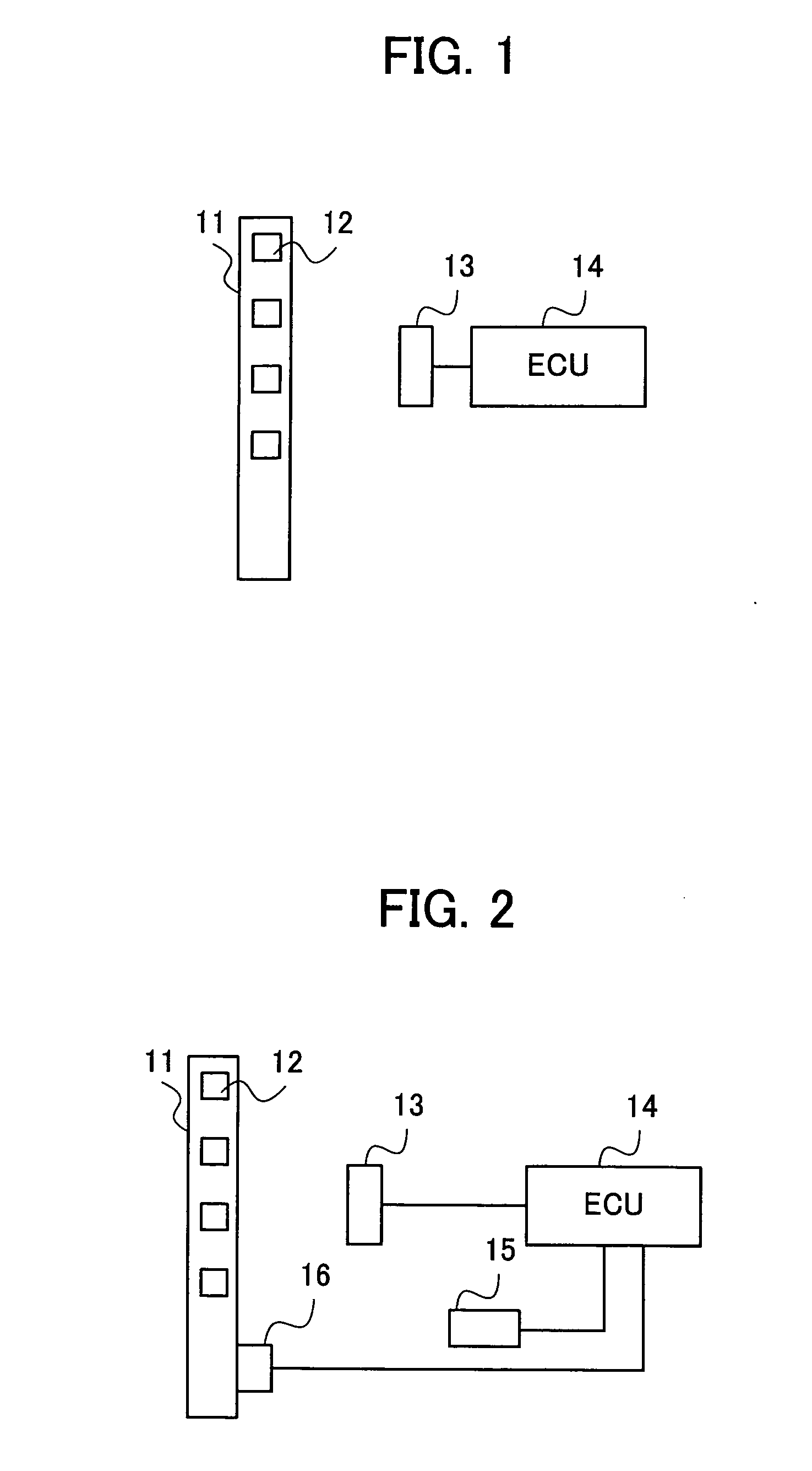
[0063]FIG. 1 is a block diagram showing one embodiment of a vehicle component tamper detection system according to the present invention. As shown in FIG. 1, in the vehicle component tamper detection system according to the present embodiment, a vehicle component 11 to be detected (hereinafter referred to as detection target component 11) is provided with a radio frequency identification integrated circuit (RFID) 12 attached thereto. In this embodiment, a radio signal from the RFID 12 attached to the detection target component 11 (or identification data stored in the RFID 12) is received wirelessly by a proper receiver 13 in a timely manner, and then transmitted to an ECU 14.

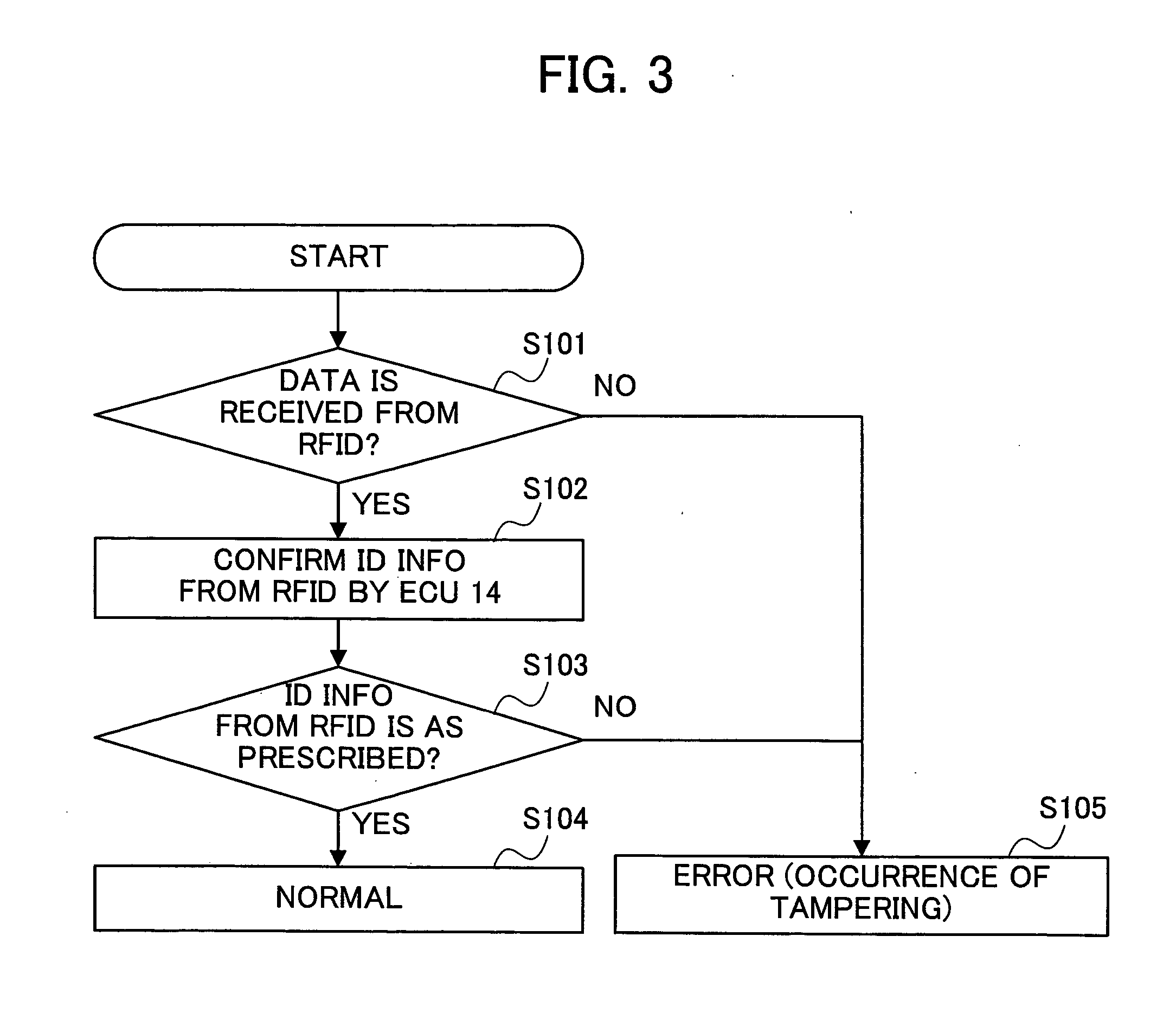
[0064] In cases in which, because the radio signal from the RFID 12 contains identification information, the ECU 14 detects whether or not a proper detection target component is mounted by reading t...


PUM


Abstract

A vehicle component tamper detection system is provided capable of appropriately preventing tampering from occurring, and of facilitating and ensuring detection of such tampering when it occurs, while maintaining flexibility in layout and in manufacturing processes. The present invention omits wiring between an RFID 12 and an ECU 14 by employing a small radio frequency identification integrated circuit (RFID) to wirelessly transmit signals to a receiver 13. With this configuration, the present invention contributes to increased layout flexibility as well as a reduction in assembly steps and manufacturing costs. Furthermore, because the RFID 12 is small, the RFID 12 may be mixed in slurry and disposed at an inconspicuous portion of a detection target component 11. Subsequently, it is possible to hinder visual confirmation of the RFID 12, thereby making the tampering itself difficult.

Description

[0001] This application is based on and claims the benefit of priority from Japanese Patent Application No. 2005-210660, filed on 20 Jul. 2005, the content of which is incorporated herein by reference. BACKGROUND OF THE INVENTION [0002] 1. Field of the Invention [0003] The present invention relates to a vehicle component tamper detection system for anti-tampering of a vehicle component of an automobile. [0004] 2. Related Art [0005] Presently, with growing concerns about environmental problems, a study has been conducted on a technique of air quality improvement in which a radiator applied with a catalyst for causative agents of photochemical smog (such as ozone) is installed in a vehicle, and such a vehicle is driven. Simply driving this type of vehicle may purify the surrounding air, and thus, the environment may be improved. [0006] However, in radiators such as these (e.g. a radiator coated with an ozone catalyst), just the cost of the portion that has been coated with the catalys...

Claims


Application Information

Patent Timeline
Patent Type & Authority Applications(United States)
IPC IPC(8): G08B13/14B60R99/00
CPCB60R25/00B60R2325/105G08B13/2451G08B13/2485G07B15/063
Inventor INOUE, NARIZANEINABA, KOICHIEGUCHI, TSUYOSHIOKAYAMA, TATSUYAMIYAUCHI, ATSUHIRO
Owner HONDA MOTOR CO LTD
Why Eureka
Try Eureka