Flow completion apparatus

a technology of flow completion and flow tube, which is applied in the direction of valve operating means/release devices, wellbore/well accessories, sealing/packing, etc., can solve the problems of increasing the cost of completing and maintaining the well, and affecting the safety of the operation of the well. , to achieve the effect of saving time and cos

Inactive Publication Date: 2006-04-11
FMC TECH INC
View PDF41 Cites 51 Cited by
  • Summary
  • Abstract
  • Description
  • Claims
  • Application Information

AI Technical Summary

Benefits of technology

[0013]It may therefore be seen that the annulus bore in the tubing hanger provides a convenient means for connecting the tubing annulus with an annulus port in a THRT. In addition, the annulus port provides a closed path between the annulus bore and a BOP choke and kill line. Thus, the flow of fluid between the tubing annulus and the BOP choke and kill line will be restricted by the annulus bore and the THRT. Consequently, this flow will not erode or contaminate the central bore of the tubing spool.
[0014]In accordance with yet another aspect of the present invention, a first barrier between the well bore and the environment is provided by both the first closure member in the production bore and the first annular seal between the tubing hanger and the tubing spool. In addition,

Problems solved by technology

Consequently, the tree cap is usually too heavy to be installed by a remotely operated vehicle (“ROV”) and must instead be lowered from the surface vessel on a specially designed tree cap running tool.
Each such trip typically requires a significant amount of valuable rig time to complete, which necessarily increases the cost of completing and maintaining the well.
In addition, during retrieval of the THRT prior to installation of the tree cap, debris within the riser often falls into the central bore of the tubing spool above the tubing hanger.
Left unattended, this debris could foul the sealing surfaces of the central bore and thereby prevent the t

Method used


Image

  • Flow completion apparatus
  • Flow completion apparatus
  • Flow completion apparatus

Examples


Embodiment Construction

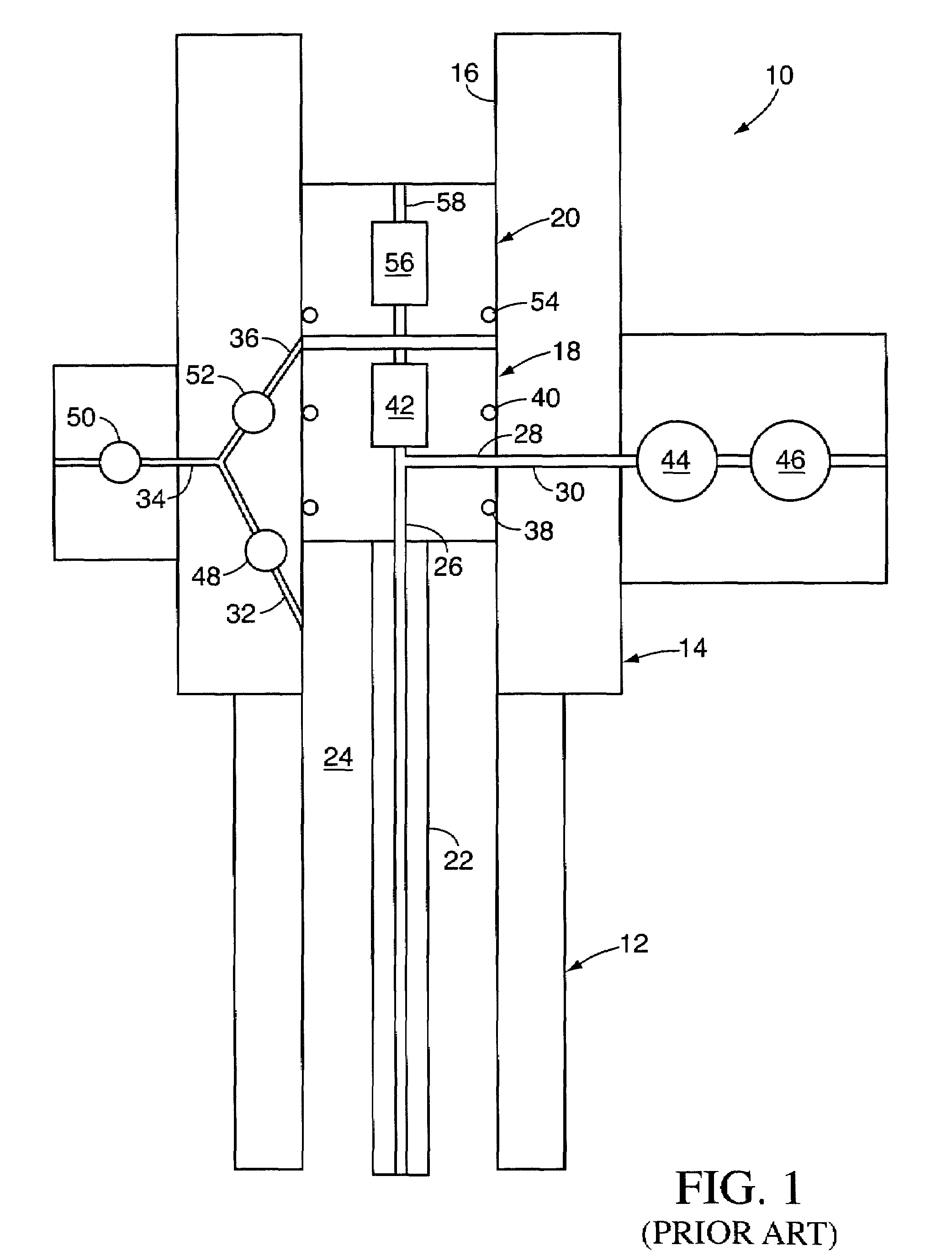
[0039]Referring to FIG. 1, a prior art horizontal-type flow completion assembly 10 is shown to comprise a wellhead housing 12 which is installed at the upper end of a well bore (not shown), a tubing spool 14 which is connected and sealed to the top of the wellhead housing and which comprises a central bore 16 extending axially therethrough, a generally annular tubing hanger 18 which is suspended from a shoulder (not shown) located in the central bore, and a tree cap 20 which is installed in the central bore above the tubing hanger. The tubing hanger 18 is secured to the tubing spool 14 by a lockdown mechanism (not shown) and supports at least one tubing string 22 which extends into the well bore and defines a tubing annulus 24 surrounding the tubing sting. In addition, the tubing hanger 18 includes a production bore 26 which communicates with the tubing string 22 and a lateral production passageway 28 which extends between the production bore and the outer diameter of the tubing han...


PUM


Abstract

A flow completion apparatus comprises a wellhead housing installed at an upper end of a well bore and a tubing spool connected over the wellhead housing. The tubing spool includes a central bore extending axially therethrough, a production outlet communicating with the central bore and an annulus passageway communicating with the tubing annulus. A tubing hanger is supported in the central bore and includes a production bore extending axially therethrough and a production passageway communicating between the production bore and the production outlet. The tubing spool comprises a workover passageway extending between the annulus passageway and a portion of the central bore located below the top of the tubing hanger. Furthermore, the tubing hanger comprises an annulus bore extending between the workover passageway and the top of the tubing hanger.

Description

[0001]This application is a continuation-in-part of U.S. patent application Ser. No. 09 / 815,430 filed on Mar. 22, 2001, now U.S. Pat. No. 6,612,368, which is based on U.S. Provisional Patent Application No. 60 / 192,124 filed on Mar. 24, 2000 and U.S. Provisional Patent Application No. 60 / 268,329 filed on Feb. 12, 2001.BACKGROUND OF THE INVENTION[0002]The present invention relates to a flow completion apparatus for producing oil or gas from a subsea well. More particularly, the invention relates to a flow completion apparatus which comprises a tubing hanger having an annulus bore which is adapted to communicate with an annulus port in a tubing hanger running tool to provide for fluid communication between the tubing annulus and the choke and kill line of a blowout preventer which is installed over the tubing hanger during installation and workover of the flow completion apparatus.[0003]Flow completion assemblies for producing oil or gas from subsea wells are generally categorized as e...

Claims


Application Information

Patent Timeline
IPC IPC(8): E21B33/03E21B33/035E21B33/00E21B33/04E21B33/043E21B33/064E21B34/04E21B34/10E21B43/013F16K3/02F16K31/122
CPCE21B33/0355E21B33/04E21B33/043E21B33/064E21B34/04E21B34/10F16K31/1225F16K3/02F16K3/0218F16K3/0254F16K3/029E21B43/013E21B2033/005E21B2200/01E21B33/0353
Inventor KENT, RICHARD D.TIERNEY, MICHAEL R.GLIDDEN, GREGORY L.CUNNINGHAM, CHRISTOPHER E.BARTLETT, CHRISTOPHER D.
Owner FMC TECH INC
Why Eureka
Try Eureka