Air-oil seal

a technology of air-oil and seals, applied in the field of seals, can solve the problems of significantly reducing the sealing capability, shaved off and ingested runner particles, and affecting the sealing effect of the runner

Active Publication Date: 2006-04-11
PRATT & WHITNEY CANADA CORP
View PDF22 Cites 37 Cited by
  • Summary
  • Abstract
  • Description
  • Claims
  • Application Information

AI Technical Summary

Problems solved by technology

The relative rotation between the knife edges and the runner of labyrinth seals, however, can tend to cause rubbing wear on the runner surface, which can eventually lead to particles of the runner being shaved off and ingested into an adjacent bearing supporting the shaft.
Knife edge wear also results.
These rubs can significantly reduce the sealing capability and ingested particles can also damage bearings, gears and / or other components adjacent to such seal if these components ingest the particles.

Method used


Image

  • Air-oil seal
  • Air-oil seal

Examples


Embodiment Construction

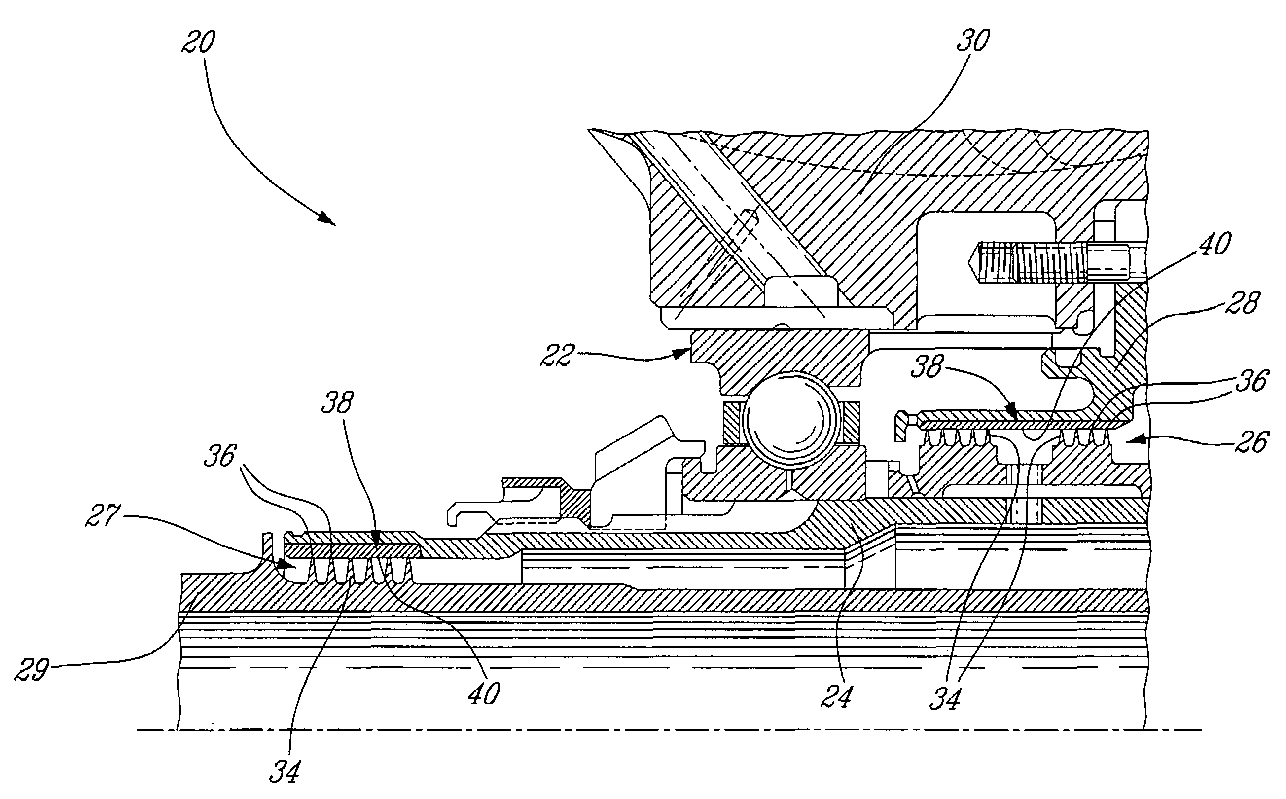
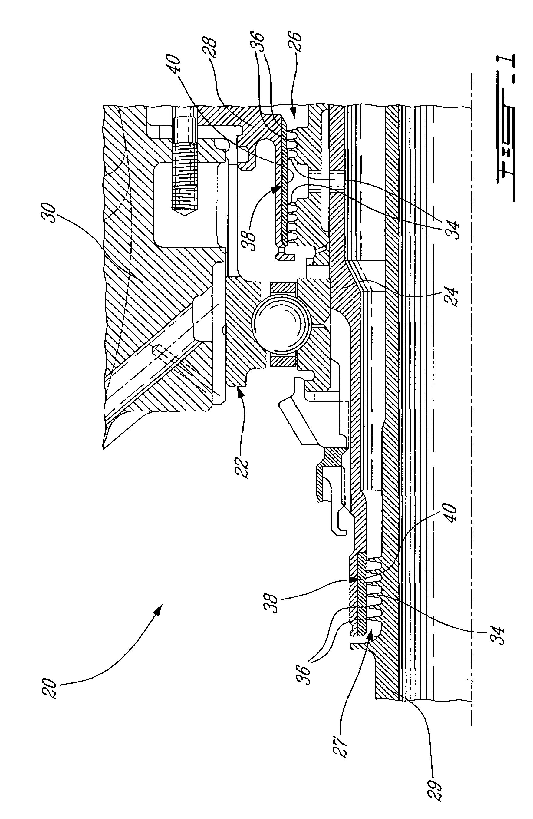
[0011]Referring to FIG. 1, a shaft bearing assembly 20 comprises generally at least one a bearing 22 supporting a rotating shaft 24 and at least one labyrinth seal 26 providing sealing between the rotating shaft 24 and an adjacent element 28, such as a portion of the stationary outer casing 30. In the embodiment depicted in FIG. 1, a second labyrinth seal 27 is provided between the rotating shaft 24 and a second rotating shaft 29 disposed concentrically within the rotating shaft 24. The labyrinth seals 26, 27 generally comprise a plurality of knife edges 34 which rotate with the shaft relative to a juxtaposed runner 38. Tips 36 of the knife edges are disposed adjacent to the runner surface 40 of the runner 38 in very tight clearance thereto such that a substructure fluid seal is provided there between. Although generally the knife edges are disposed on a shaft which rotates within a stationary surrounding runner, it is to be understood that the converse is also possible, namely that...


PUM


Abstract

An air-oil seal having a runner surface comprising at least one component selected from the group consisting of: polyetheretherketone; polyetherimide; polyphenylene sulfide; and polyetherketoneketone.

Description

TECHNICAL FIELD[0001]The invention relates generally to rotary seals and, more particularly, to a seal for sealing a rotating shaft.BACKGROUND OF THE ART[0002]Labyrinth seals are often used as air-oil seals to provide sealing of rotating shafts of bearing compartments and gear cases, etc. Labyrinth seals typically comprise knife edges or teeth or fins which rotate relative to a surrounding seal land or runner, the knife edges having tight tip clearances with a surface of the land or runner. The relative rotation between the knife edges and the runner of labyrinth seals, however, can tend to cause rubbing wear on the runner surface, which can eventually lead to particles of the runner being shaved off and ingested into an adjacent bearing supporting the shaft. Knife edge wear also results. These rubs can significantly reduce the sealing capability and ingested particles can also damage bearings, gears and / or other components adjacent to such seal if these components ingest the partic...

Claims


Application Information

Patent Timeline
Patent Type & Authority Patents(United States)
IPC IPC(8): F16J15/453
CPCF16J15/445
Inventor CHEUNG, KIN-LEUNGHUNG, WILLIAM TING-CHEL
Owner PRATT & WHITNEY CANADA CORP
Why Eureka
Try Eureka