High temperature resistant insulation for pipe

a technology of high temperature resistance and pipe, applied in the direction of flexible pipes, rigid pipes, non-disconnectible pipe joints, etc., can solve the problems of reducing or losing production, requiring the replacement of sections of pipelines or entire systems with corresponding asset value loss, and affecting the performance of the pipe, etc., to achieve high compressive strength, low thermal conductivity, and high thermal stability

Active Publication Date: 2013-03-19
SHAWCOR LTD
View PDF133 Cites 34 Cited by
  • Summary
  • Abstract
  • Description
  • Claims
  • Application Information

AI Technical Summary

Benefits of technology

[0014]In one aspect, the present invention provides insulating and protective coatings comprising at least one thermal insulation layer of a high temperature resistant thermoplastic, containing gas bubbles, and having the desired properties of low thermal conductivity, high thermal stability and high compressive strength at elevated temperatures and pressures.
[0022]In a further aspect, the present invention provides insulated high-temperature transport conduit for use in offshore, deep water environments, the conduit comprising: (a) a continuous steel pipe made up of one or more pipe sections, wherein the steel pipe has an outer surface and an inner surface; and (b) a first layer of thermal insulation provided over the outer surface of the steel pipe, wherein the first layer of thermal insulation is comprised of a high temperature resistant thermoplastic having low thermal conductivity, high thermal softening point, high compressive strength and high compressive creep resistance.

Problems solved by technology

Both of these phenomena are related to the temperature of the fluid, and in extreme cases the conduit can become severely constricted or even blocked.
This in turn can lead to reduced or lost production.
In particularly serious cases this may lead to the need to replace sections of pipeline or entire systems with corresponding loss of asset value.
Hence, the traditional thermal insulation foam technology used in shallow waters and the associated design and test methodologies may not be applicable to deep-water projects.
In cases of long pipe tiebacks, for example subsea-to-beach tiebacks, and in cases where the service temperature is above approximately 150° C., there exist limitations with current technology that may hinder the successful development of offshore, deep water oil or gas fields.
Limitations and deficiencies of these technologies include:Relatively high thermal conductivity of known insulating systems, necessitating excessively thick coatings to achieve the required insulation performance, leading to potential difficulties in foam processing, potential issues with residual stress, difficulties during pipe deployment, and sea-bed instability.Insufficient resistance to temperatures above 130° C., resulting in compression and creep resistance issues in high temperature installations at high water depths.Excessive costs due to poor material cost versus performance capabilities or high transportation and deployment costs.Deployment and operation disadvantages with Pipe-In-Pipe systems due to weight factors leading to buckling and weld failure if not properly addressed, and the need for high gripping loads during pipe laying.

Method used


Image

  • High temperature resistant insulation for pipe
  • High temperature resistant insulation for pipe
  • High temperature resistant insulation for pipe

Examples


example 1

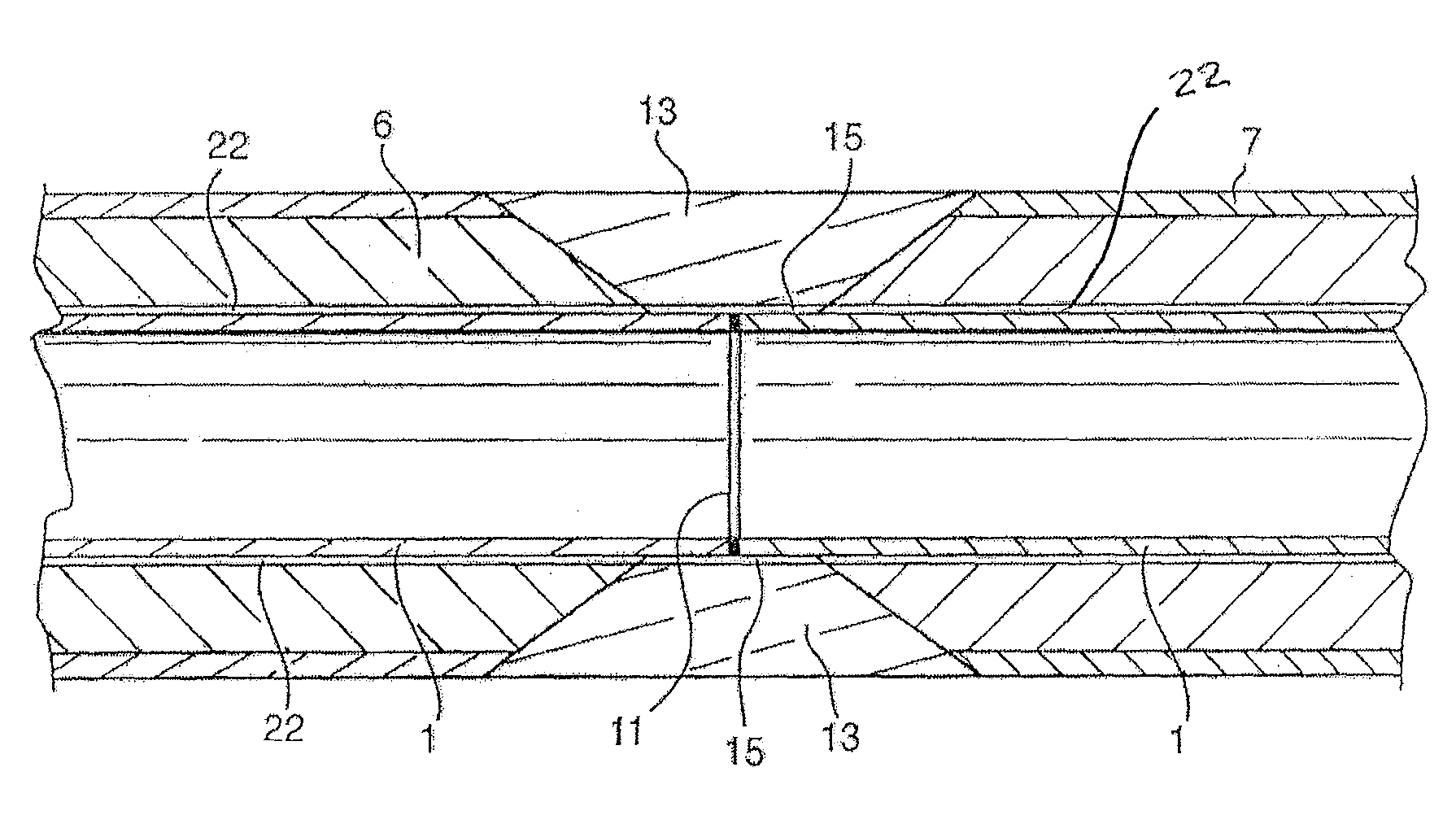
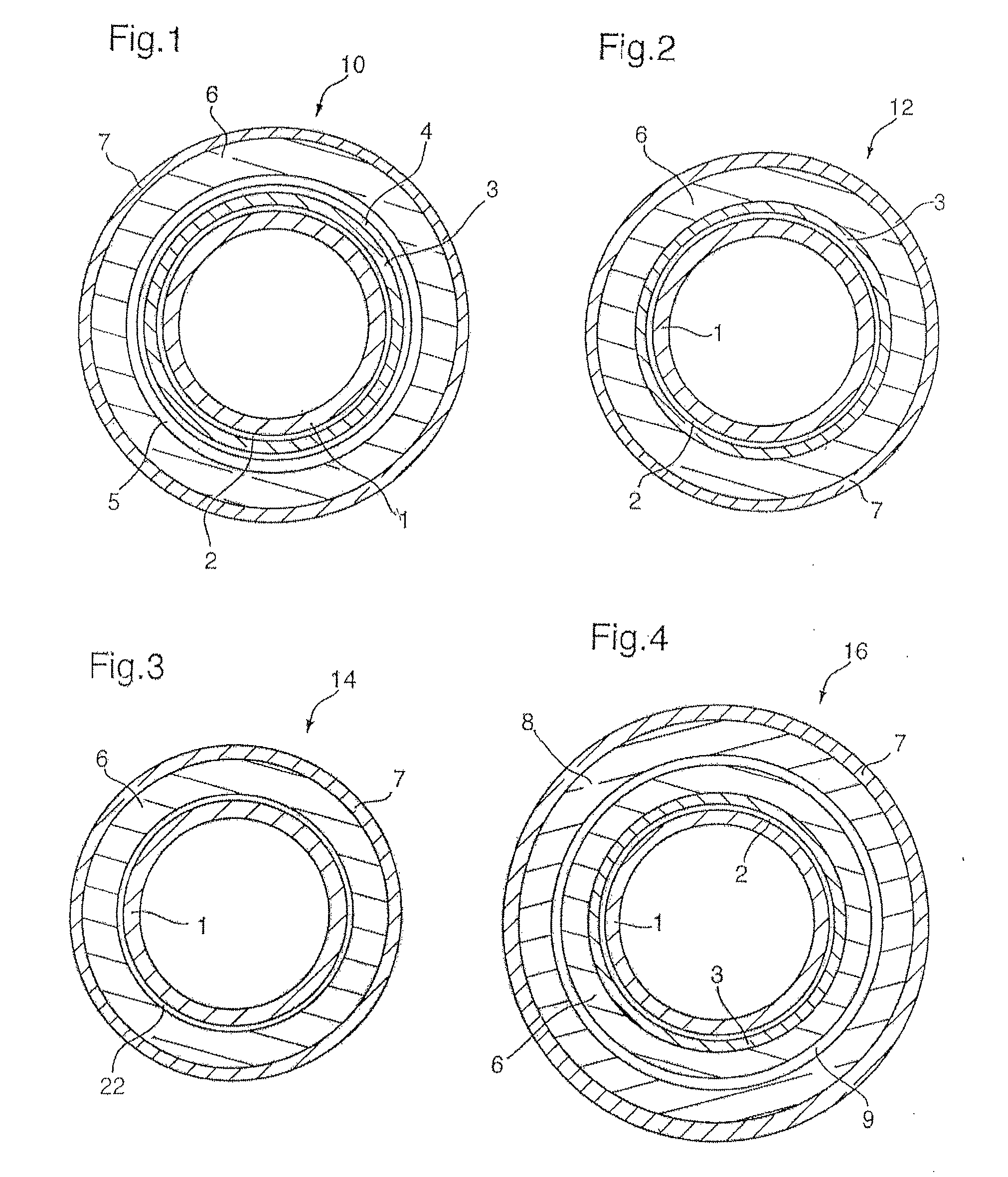
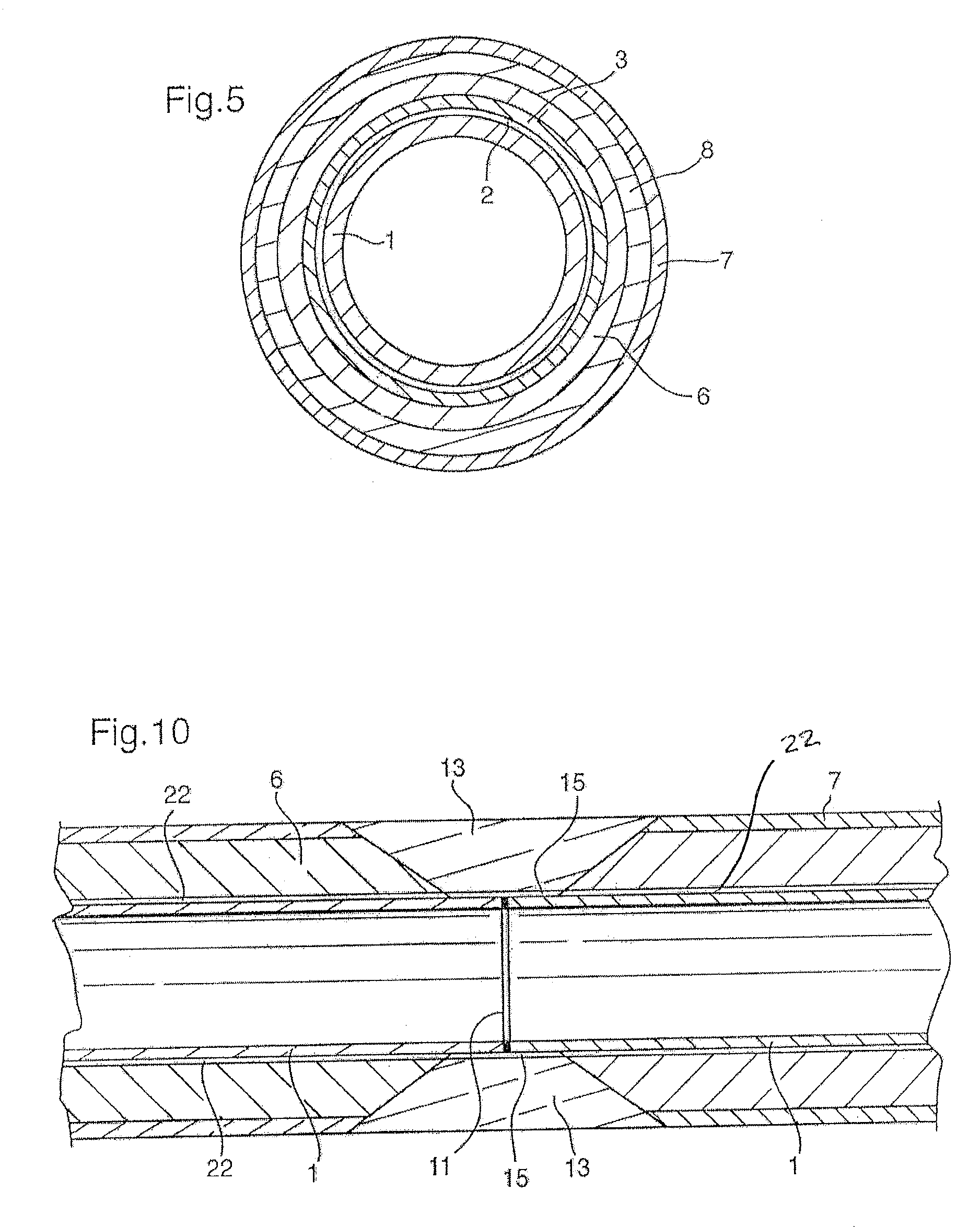
[0143]In this example a steel pipe 1 is provided with a three layer corrosion protection coating as described above in connection with FIG. 1, comprising a corrosion protection layer 2, an adhesive layer 3 and a topcoat 4. The steel pipe 1, which was surface-blasted and cleaned, had an outside diameter of 140 mm and wall thickness of 10 mm. The pipe 1 was pre-heated to a temperature of 200° C. and spray-coated with a 0.300+ / −0.100 mm thick layer 2 of fusion bonded high temperature epoxy powder (density 1400+ / −100 g / l), followed immediately by the extrusion on top of the epoxy of a 0.300+ / −0.200 mm layer 3 of a high temperature modified styrene-maleic anhydride copolymer adhesive (density 1.060 g / cm3 and melt flow rate 0.6 g / 10 min) and a 6.0+ / −1.0 mm topcoat 4 of solid polyphenylene oxide-polystyrene blend (density 1.060 g / cm3 and melt flow rate 8 g / 10 min.) at melt temperatures of 220° C. and 260° C., respectively. Extrusion of adhesive layer 3 and topcoat 4 was accomplished in seq...

example 2

[0144]The corrosion-protected pipe produced in Example 1 was further coated with a 20.0+ / −1.0 mm layer 6 of the same solid polyphenylene oxide-polystyrene blend (degree of foaming=0%) of topcoat 4 using an extruder equipped with a sheet die by preheating the outer surface of said corrosion-protected pipe to a temperature of around 220° C., and wrapping the polyphenylene oxide-polystyrene blend at a melt temperature of 260° C. on top of the preheated outer surface. The insulated pipe thus produced was tested for the properties noted in Table 3.

example 3

[0145]Using the coating procedure described in Example 2, the corrosion protected pipe produced in Example 1 was further coated with a 30.0+ / −1.0 mm layer 6 of the polyphenylene oxide-polystyrene blend of Example 1 foamed to a density of 0.945 g / cm3 (degree of foaming=10%) using 0.5% by weight of an endothermic chemical foaming agent, and an outer 5.0+ / −1.0 mm. layer 7 of solid high impact polystyrene modified with polyethylene (density 1.020 g / cm3 and melt flow index 4.0 g / 10 min.). The insulated pipe thus produced was tested for the properties noted in Table 3.


PUM

PropertyMeasurementUnit
Vicat softening pointaaaaaaaaaa
temperaturesaaaaaaaaaa
temperatureaaaaaaaaaa

Abstract

A polymeric composition for insulating fluid and / or gas transport conduits, such as off-shore oil and gas pipelines operating at temperatures of 130° C. or higher in water depths above 1,000 meters. The outer surface of the conduit is provided with at least one layer of solid or foam insulation comprising a high temperature resistant thermoplastic having low thermal conductivity, high thermal softening point, high compressive strength and high compressive creep resistance. The high temperature resistant thermoplastic is selected from one or more members of the group comprising: polycarbonate; polyphenylene oxide; polyphenylene oxide blended with polypropylene, polystyrene or polyamide; polycarbonate blended with polybutylene terephthalate, polyethylene terephthalate, acrylonitrile butadiene styrene, acrylonitrile styrene acrylate, or polyetherimide; polyamides, including polyamide 12 and 612 and elastomers thereof; polymethylpentene and blends thereof; cyclic olefin copolymers and blends thereof; and, partially crosslinked thermoplastic elastomers, also known as thermoplastic vulcanizates or dynamically vulcanized elastomers.

Description

FIELD OF THE INVENTION[0001]The present invention relates to polymeric compositions for insulating fluid and / or gas transport conduits, transport conduits insulated with these compositions, and methods for the production and application thereof. More particularly, the polymeric compositions according to the invention comprise high temperature resistant thermoplastics having low thermal conductivity, high thermal softening point and high compressive creep resistance for use in the thermal insulation of fluid and / or gas transport conduits such as oil and gas pipelines.BACKGROUND OF THE INVENTION[0002]There is increasing demand in the oil and gas industry for higher performance thermal coatings to insulate and protect off-shore transport conduits operating at temperatures of 130° C., or higher, in water depths above 1,000 meters. In order to maintain the conduit at the required operating temperatures at these depths, the coatings must have low thermal conductivity to prevent the format...

Claims


Application Information

Patent Timeline
Patent Type & Authority Patents(United States)
IPC IPC(8): F16L9/14
CPCB32B15/08F16L13/0272F16L58/1054F16L59/143F16L59/20F16L59/028Y10T428/1393B32B5/18B32B7/12B32B15/18B32B27/065B32B27/08B32B27/16B32B27/281B32B27/285B32B27/286B32B27/30B32B27/32B32B27/34B32B27/36B32B27/365B32B27/38B32B27/42B32B1/08B32B2266/0228B32B2266/025B32B2270/00B32B2274/00B32B2307/304B32B2307/306B32B2307/714B32B2597/00
Inventor JACKSON, PETERJACKSON, ADAMWAN, EILEENHEGDAL, JAN PEDER
Owner SHAWCOR LTD
Why Eureka
Try Eureka