Recording apparatus

Active Publication Date: 2006-04-11
CANON KK
View PDF2 Cites 4 Cited by
  • Summary
  • Abstract
  • Description
  • Claims
  • Application Information

AI Technical Summary

Benefits of technology

[0020]Also, according to the present invention, the holding member and the projected portion of the carriage overlap each other with respect to the scanning direction of the carriage, and the holding member and the attenuating member, and the projected portion of the carriage and the attenuating member are substantially in fitted relationship with each other, whereby the effect of suppressing the vibrations of the carriage can be heightened.
[0021]Also, according to the present invention, the holding member and the projected portion of the carriage overlap each other with respect to the projecting direction of the projected portion, and the holding member and the attenuating member, and the projected portion of the carriage and the attenuating member are substantially in fitted relationship with each other, whereby the effect of suppressing the vibrations of the carriage can be heightened.
[0022]Also, according to the present invention, the recording apparatus further has a mounting member for mounting the holding member on the carriage, and the mounting member does not contact with the carriage, but operates integrally with the holding member, whereby the carriage and the holding member can be reliably mounted wit

Problems solved by technology

Also, the degree of freedom is secured by only the compression allowance of the attenuating member and therefore, it is difficult for phase deviation to occur with respect to the sc

Method used


Image

  • Recording apparatus
  • Recording apparatus
  • Recording apparatus

Examples


first embodiment

(First Embodiment)

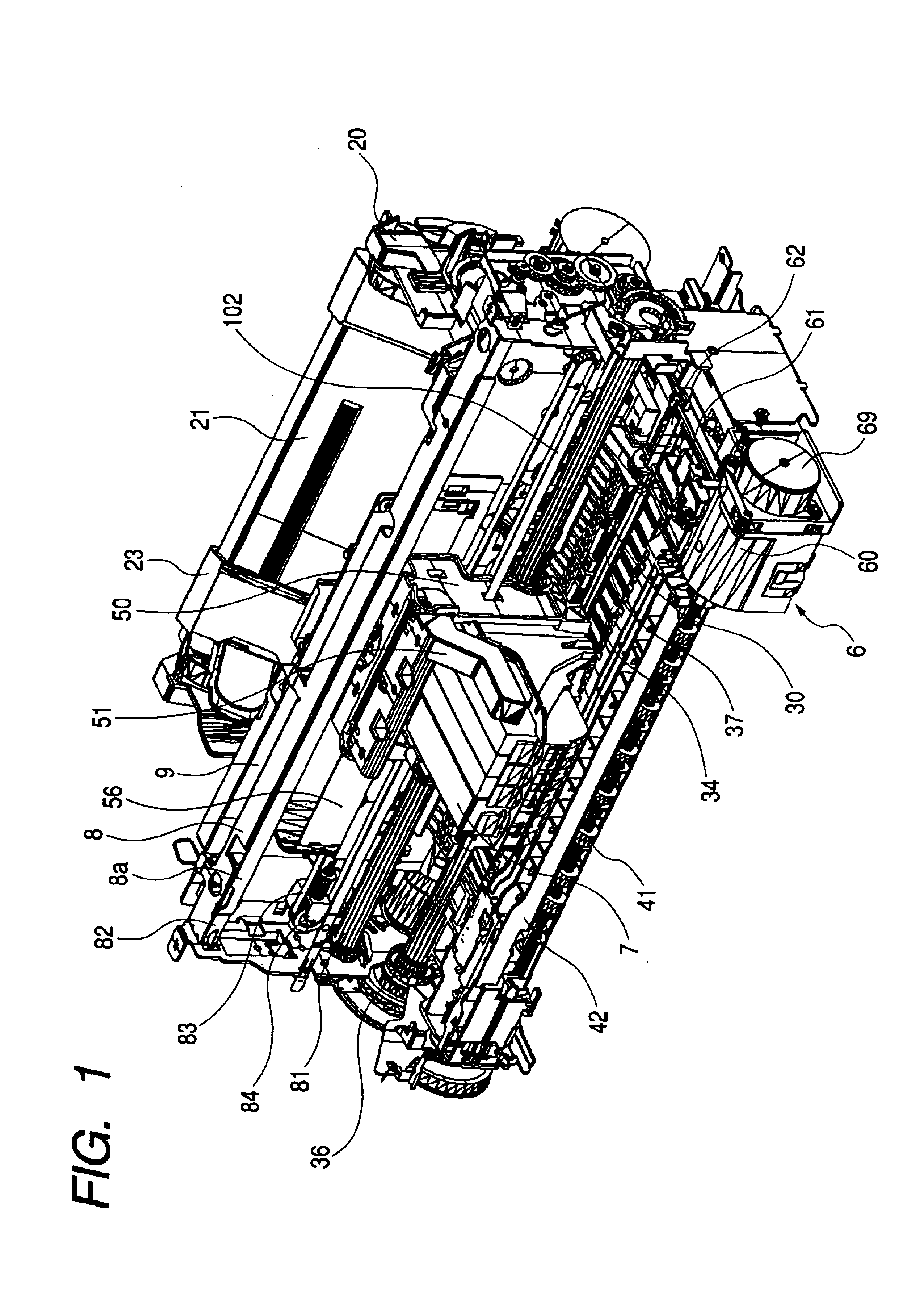
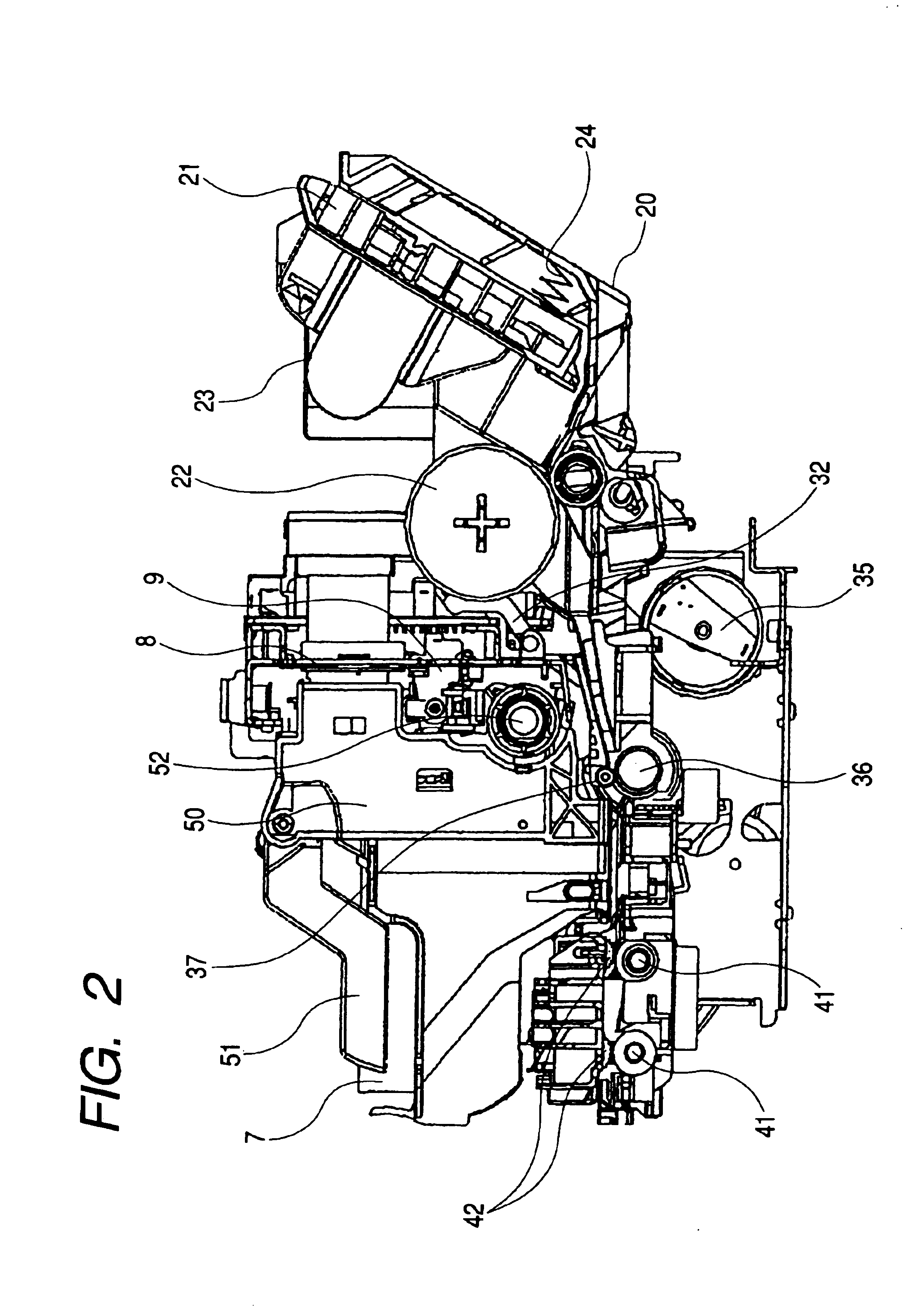
[0033]The structure of the recording apparatus of the present invention is first schematically shown in FIGS. 1 and 2. FIG. 1 is a perspective view showing the general construction of a recording apparatus according to an embodiment suitable for the present invention, and FIG. 2 is a side cross-sectional view of the recording apparatus.

[0034]The recording apparatus 1 of the form shown in FIG. 1 is an ink jet recording apparatus of a serial scan type, and comprises a sheet feeding portion having an automatic feeder, a sheet conveying portion, a sheet discharging portion, a carriage portion 5 and a cleaning portion 6. These will be divided into items and will be schematically described in succession. Also, while in the present embodiment, description will be made with the ink jet recording apparatus taken as an example, the present invention is not restricted to the ink jet recording type, but can be applied to any recording apparatus of the serial scan type. Also, w...

second embodiment

(Second Embodiment)

[0052]A second embodiment of the present invention will now be described with respect to its difference from the first embodiment.

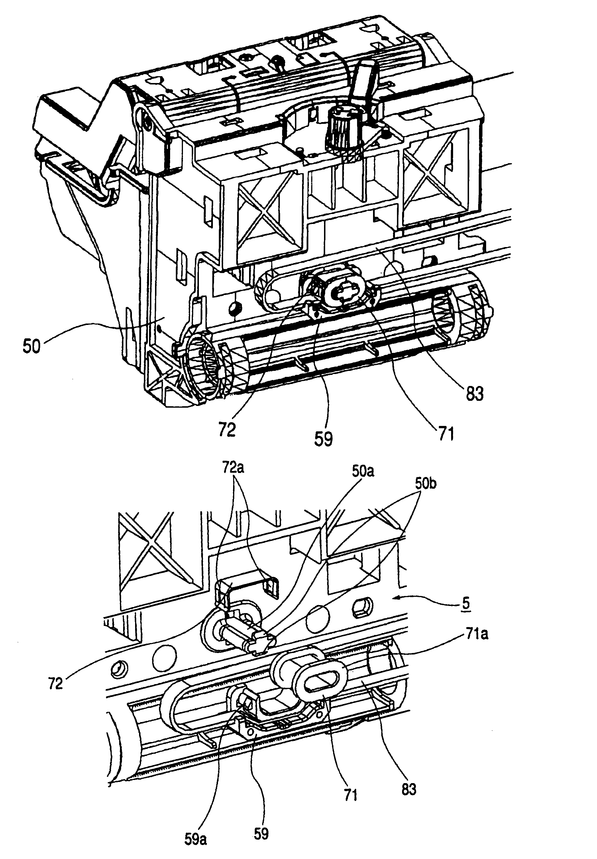
[0053]FIG. 5 shows that portion of a carriage portion in the second embodiment of the present invention, which is concerned in drive transmission. However, FIG. 5 represents only the projected portion 50a of the carriage 50 and the belt holder 59 shown in FIGS. 3 and 4, and does not show the damper 71 and the timing belt 83.

[0054]In the present embodiment, as shown in FIG. 5, the design gap “d” between the projected portion 50a of the carriage 50 and the belt holder 59 in the scanning direction of the carriage is made smaller than the thickness “t” of the damper 71. According to the present embodiment, there is realized such a dimensional relation that the damper 71 is compressed in advance, and the oscillation of the carriage with respect to the scanning direction of the carriage can be suppressed more effectively.

third embodiment

(Third Embodiment)

[0055]A third embodiment of the present invention will now be described with respect to its differences from the first embodiment.

[0056]FIG. 6 shows a portion of a carriage portion in the third embodiment of the present invention, which portion is concerned in drive transmission. Hatchings in FIG. 6 represent a cross-section.

[0057]As described in the first embodiment, in the connecting structure for the carriage portion and the timing belt, the driving force from the carriage motor is transmitted to the belt holder 59 through the timing belt 83, and is further transmitted from the belt holder 59 to the damper 71 and the carriage 50. In this form, a force, which rotates the belt holder 59, is applied during the start.

[0058]As a countermeasure for this, as shown inFIG. 6, convex portions 50c are provided at two locations along the scanning direction of the carriage on each of two upper and lower sides of the projected portion 50a of the carriage 50, which convex port...


PUM


Abstract

A recording apparatus for effecting recording on a recording medium by a recording head includes a carriage for reciprocally scanning with the recording head carried thereon, a guide member for guiding the reciprocal scanning of the carriage, a drive source for driving the reciprocal scanning of the carriage, a transmitting member for transmitting a driving force from the drive source to the carriage, a holding member for holding the transmitting member, a projected portion disposed on the carriage and having the holding member mounted thereon, and an attenuating member for attenuating vibrations from the drive source between the carriage and the holding member, the attenuating member being of a shape surrounding the projected portion of the carriage, and the holding member holding the transmitting member being mounted on the projected portion with the attenuating member interposed therebetween.

Description

BACKGROUND OF THE INVENTION[0001]1. Field of the Invention[0002]The invention relates to a recording apparatus for effecting recording on a recording medium by a recording head.[0003]2. Description of Related Art[0004]A recording apparatus having the functions of a printer, a copying machine, a facsimile apparatus, etc., or a recording apparatus used as the output apparatus of compound type electronic apparatus or a work station including a computer, a word processor, etc., has such a construction that can record an image on a recording material (recording medium) such as paper or a plastic thin sheet on the basis of image information. Such recording apparatuses can be grouped into an ink jet type, a wire dot type, a thermal type, a laser beam type, etc., depending on its recording method.[0005]In a recording apparatus of a serial type adopting a serial scanning method of main-scanning in a direction intersecting with the conveyance direction (sub-scanning direction) of a recording ...

Claims


Application Information

Patent Timeline
IPC IPC(8): B41J3/00B41J2/165B41J19/20B41J19/06B41J23/00
CPCB41J23/00B41J19/06
Inventor IKEDA, YASUHIKOTAKAHASHI, SEIJIUCHIDA, KOTA
Owner CANON KK
Why Eureka
Try Eureka