AI technical title is built by Patsnap AI team. It summarizes the technical point description of the patent document.
a technology of diffractive lenses and vision correction, applied in the field of diffractive lenses for vision correction, can solve the problems of not providing two different focal distances, e.g., near and distan
Active Publication Date: 2006-04-11
APOLLO OPTICAL SYST
View PDF100 Cites 63 Cited by
Summary
Abstract
Description
Claims
Application Information
AI Technical Summary
This helps you quickly interpret patents by identifying the three key elements:
Problems solved by technology
Method used
Benefits of technology
Benefits of technology
"The present invention provides diffractive lenses that combine a multiorder diffractive structure (MOD) and a non-MOD diffractive structure (WSD) to provide bifocal lenses for distance and near vision correction. The MOD structure has multiple zones that create optical phase shifts and diffract light of different wavelengths in different orders, while the WSD structure splits light into two diffractive orders. The combination of these structures in the lens provides the base power for distance vision correction and the add power for near vision correction. The lenses can be used in various ophthalmic applications such as contact lenses, spectacle lenses, and intraocular implants."
Problems solved by technology
The MOD lenses correct for this problem, but does not provide two different focal distances, e.g., near and distant, useful for providing therapeutic bifocal corrective ophthalmic lenses.
Method used
Image
Click on the blue label to locate the original text in one second.
Reading with bidirectional positioning of images and text.
Examples
example 1
[0039]In this example, an ophthalmic lens prescription requires a correction of −7 diopters (D) for distance vision, with a +2 diopters (D) add power for near vision. Thus, the two powers (denoted by φ) of the lens are
φdistance=−7 D
φnear=−5 D(=−7 D+2 D=φdistance+φodd)
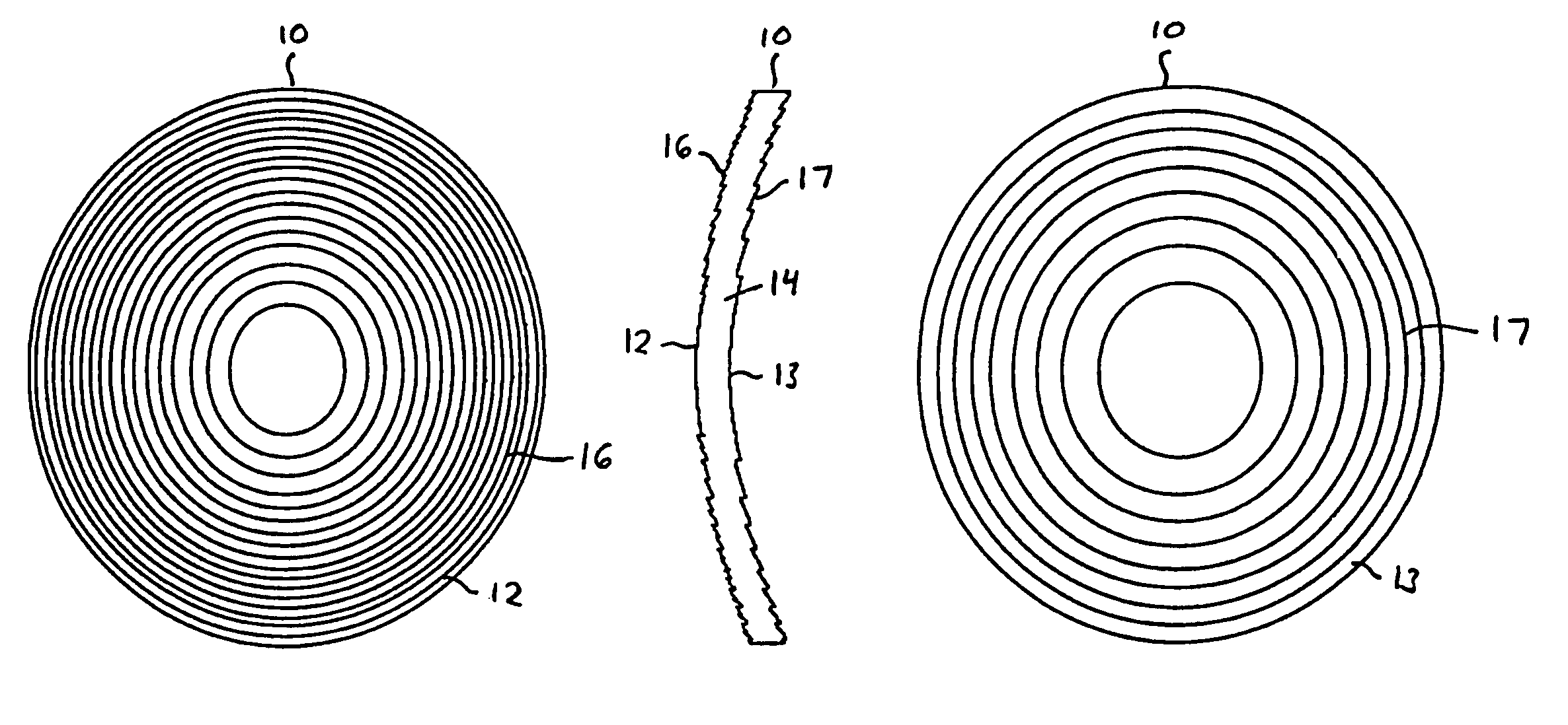
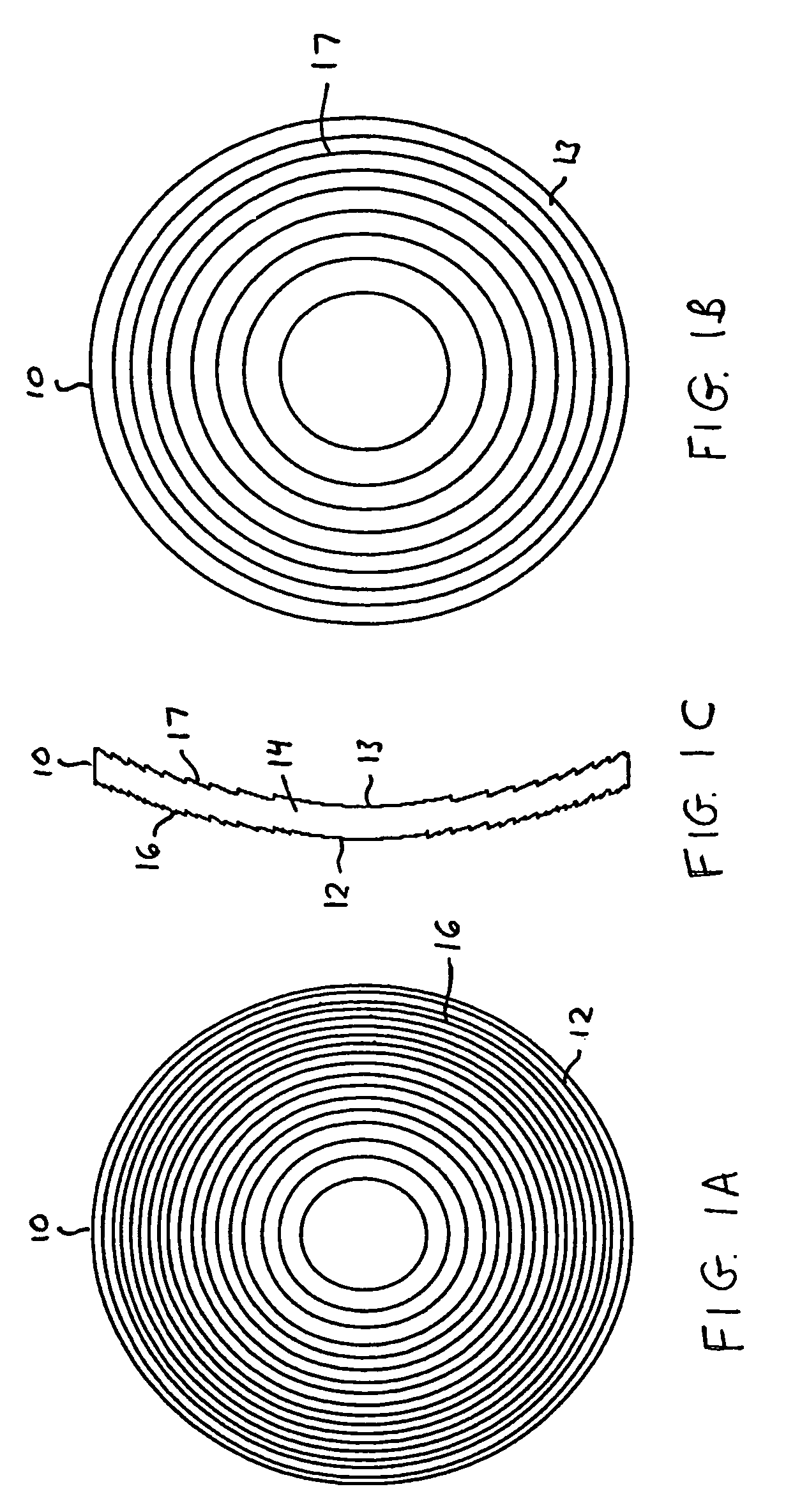
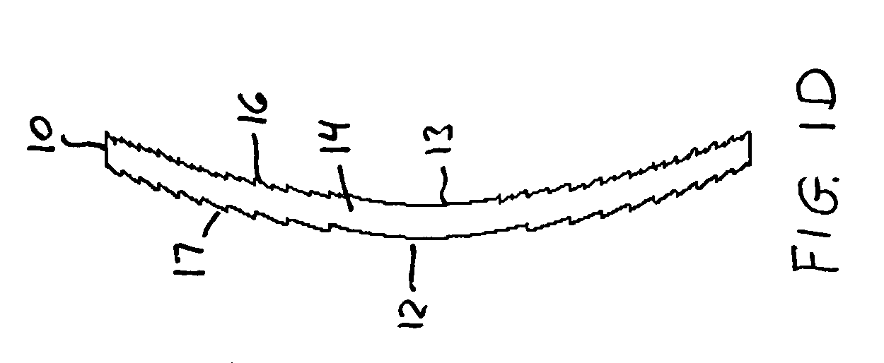
The lens will consist of a MOD structure 17 with the required distance power on one side (i.e., along surface 12 or 13) of a thin substrate providing the lens body 14, and with a WSD structure 16 with a blazed surface, operating primarily in the 0 and +1 orders, on the other side (or surface).
[0040]The radial locations (rj) of the diffractive zones of the MOD structure are given by
[0041]rj=2jpλ0ϕdistance
[See Equation (1) of incorporated U.S. Pat. No. 5,589,982, with φ0=1 / F0.]
[0042]In this example, the selected design wavelength λ0=555 m (peak of photopic response). The photopic response refers to the efficiency of the human eye's perception of light wavelengths under high illumination. If p=10, the zone radii within ...
example 2
[0051]This example has the same ophthalmic prescription (−7 D distance power, with a +2 D add power) as Example 1, but uses a WSD structure 16 having a square-wave diffractive surface. The square-wave surface introduces one-half wavelength of optical path difference (OPD) (or, equivalently, a phase shift of π radians) over half of each zone and zero OPD over the remaining half of the zone. Since the square-wave diffractive surface has appreciable energy in the +1 and −1 diffraction orders, the power of the MOD structure in this case is φMOD=−6 D and the power of the square-wave WSD surface is φSQw=+1 D. The resulting total lens powers are, as in the previous example
φdistance=φMOD−φSQW=−6 D−1 D=−7 D
φnear=φMOD+φSQW=−6 D+1 D=−5 D=φdistance+φodd
The radial locations (rj) of the diffractive zones of the MOD structure are given by
[0052]rj=2jpλ0ϕMOD
Again, the selected design wavelength λ0=555 nm (peak of photopic response). If p=10, the zone radii within a clear aperture diameter of 10 ...
PUM
Abstract
Diffractive lenses for vision correction are provided on a lens body having a first diffractive structure for splitting light into two or more diffractive orders to different focal distances or ranges, and a second diffractive structure, referred to as a multiorder diffractive (MOD) structure, for diffracting light at different wavelengths into a plurality of different diffractive orders to a common focal distance or range. In a bifocal application, the first and second diffractive structures in combination define the base power for distance vision correction and add power for near vision correction of the lens. The first and second diffractive structures may be combined on the same surface or located on different surfaces of the lens. An optical element, such as a substrate or coating, may be integrated along one or both surfaces of the lens to provide the lens with smooth outer surface(s).
Description
FIELD OF THE INVENTION[0001]The present invention relates to diffractive lenses for vision correction, and particularly to diffractive lenses for therapeutic vision correction at at least distance and near vision correction suitable for use with a variety of vision correction applications, such as intraocular implants (IOLs), contact lenses, or spectacle (eyeglass) lenses. The invention further relates to a method for providing such diffractive lenses.BACKGROUND OF THE INVENTION[0002]Multiorder diffractive (MOD) lenses are useful for bringing a plurality of spectral components of different wavelengths to a common focus, and are described in U.S. Pat. No. 5,589,982. The MOD lens has a structure of multiple annular zones having step heights defining zone boundaries, which diffract light at different wavelengths into different diffractive orders to a common focus. In contrast, viewing light of multiple different wavelengths through non-MOD diffractive multifocal lens can appear blurry ...
Claims
Application Information
Patent Timeline
Application Date:The date an application was filed.
Publication Date:The date a patent or application was officially published.
First Publication Date:The earliest publication date of a patent with the same application number.
Issue Date:Publication date of the patent grant document.
PCT Entry Date:The Entry date of PCT National Phase.
Estimated Expiry Date:The statutory expiry date of a patent right according to the Patent Law, and it is the longest term of protection that the patent right can achieve without the termination of the patent right due to other reasons(Term extension factor has been taken into account ).
Invalid Date:Actual expiry date is based on effective date or publication date of legal transaction data of invalid patent.

