Transmission-type screen and back-type projector

A transmission type, projector technology, used in projectors, instruments, lenses, etc. with built-in screens/external screens, can solve problems such as easy occurrence of ripples and easy occurrence of diffracted light, and achieves reduction of flicker, suppression of diffracted light, and suppression of Contrast drop effect

Inactive Publication Date: 2004-05-12
SEIKO EPSON CORP
View PDF1 Cites 28 Cited by
  • Summary
  • Abstract
  • Description
  • Claims
  • Application Information

AI Technical Summary

Problems solved by technology

[0007] However, in the above-mentioned transmissive screen 900, there is a problem that diffracted light easily occurs.
In addition, in the above-mentioned transmissive screen 900, there is also the problem that moiré easily occurs.

Method used


Image

  • Transmission-type screen and back-type projector
  • Transmission-type screen and back-type projector
  • Transmission-type screen and back-type projector

Examples


Embodiment 1

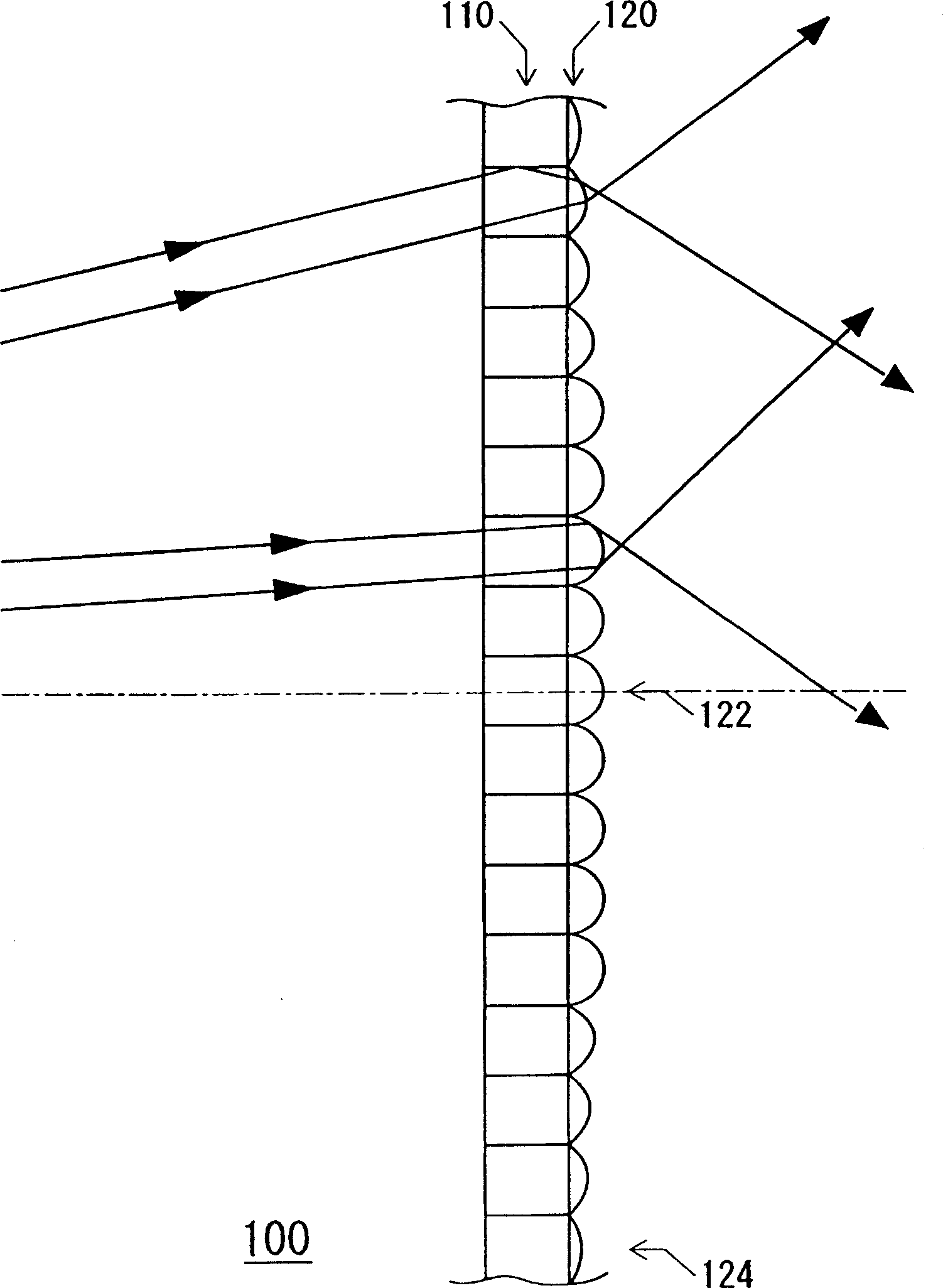
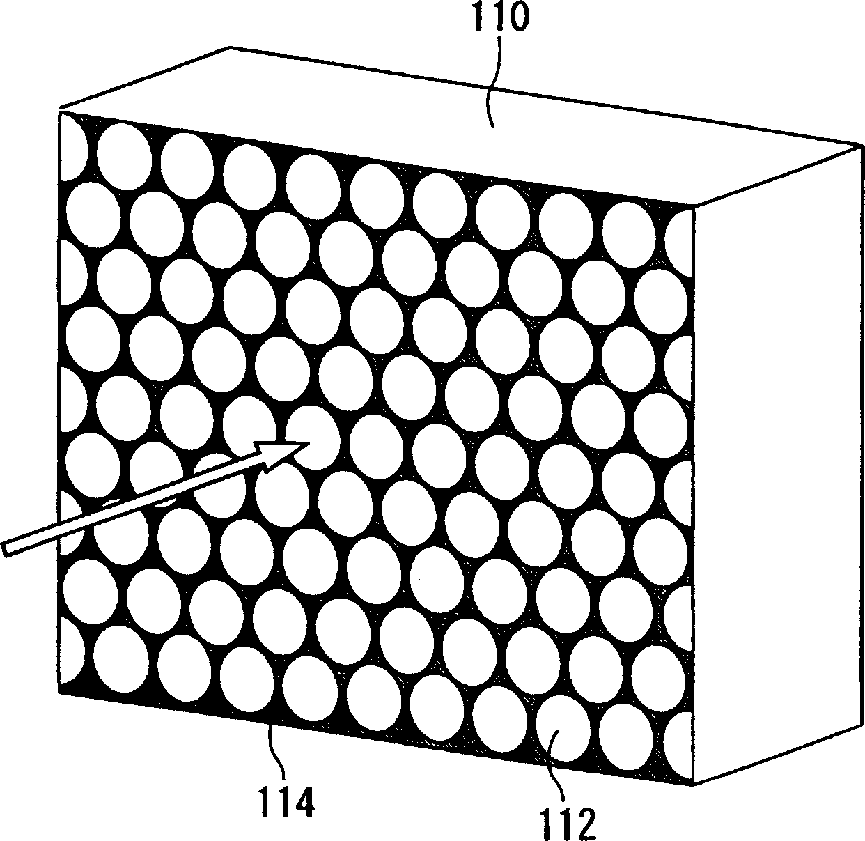
[0073] The transmissive screen of Embodiment 1 is a transmissive screen used for a rear projector. figure 1 It is a figure which shows the optical system of the transmissive screen of Example 1. also, figure 2 It is a perspective view of a light guide plate constituting a part of the transmissive screen of the first embodiment. Such as figure 1 and figure 2 As shown in , the transmissive screen 100 has: a light guide plate 110, the light guide plate is arranged as a plurality of substantially cylindrical light guide spaces with optical fibers 112; The side is used as an emission angle distribution uniformizing device for uniforming the emission angle distribution of the optical fiber emitted from the light guide plate 110 within the screen.

[0074] The microlens array 120 has a plurality of microlenses provided corresponding to the optical fibers 112 of the light guide plate 110 , and the curvature radius of these microlenses gradually increases from the center of the...

Embodiment 2

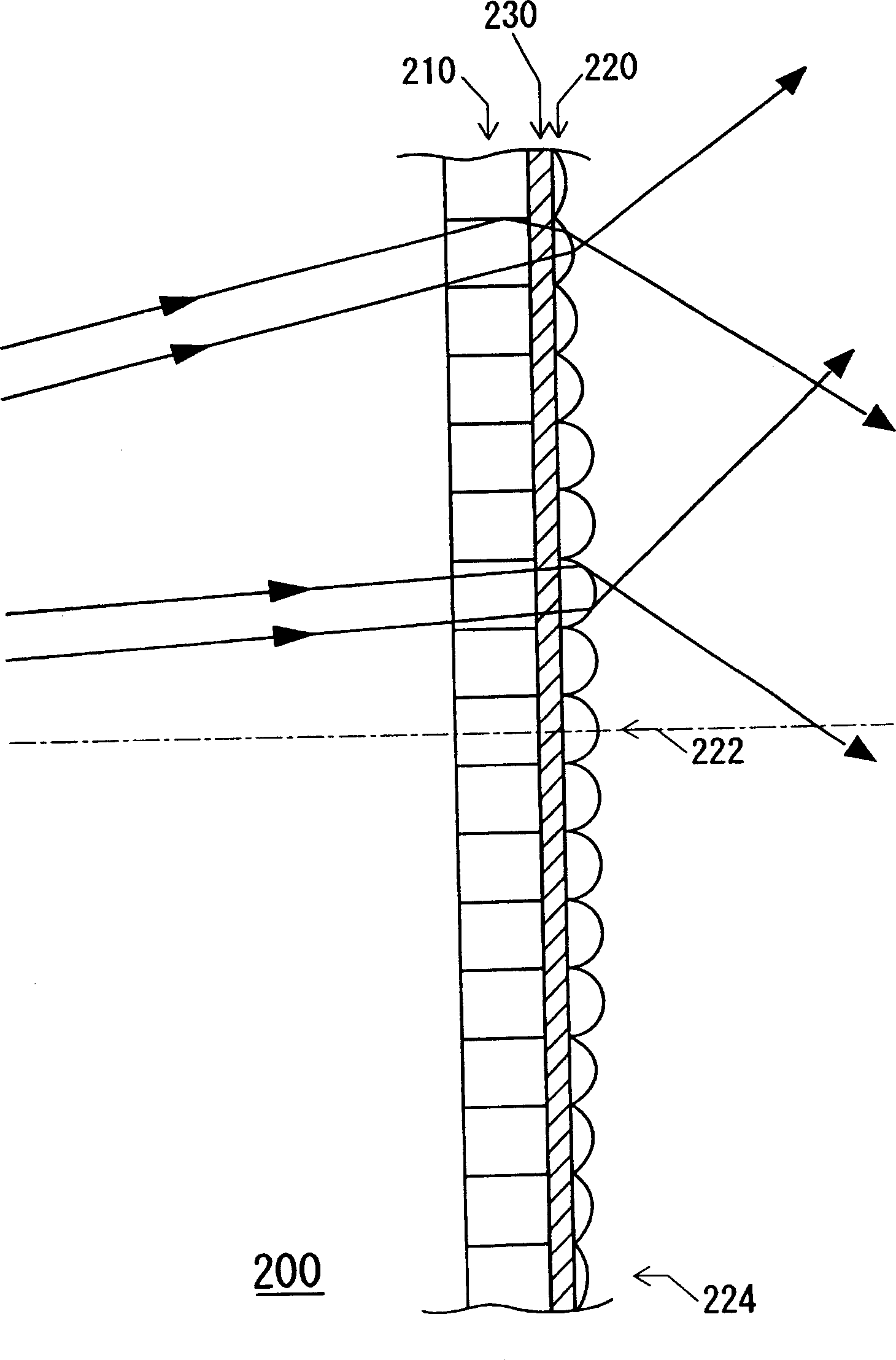
[0083] image 3 It is a figure which shows the optical system of the transmissive screen of Example 2 of this invention. Such as image 3 As shown in , the difference between the transmissive screen 200 of Embodiment 2 and the transmissive screen 100 of Embodiment 1 is that it has a light diffusion layer 230 .

[0084] That is, in the transmissive screen 100 of the first embodiment, the microlens array 220 is disposed on the exit surface of the light guide plate 110, whereas in the transmissive screen 200 of the second embodiment, only the microlens array 220 is disposed on the exit surface of the light guide plate 110. A light-diffusing layer 230 is disposed on the central portion of the surface, and a microlens array 220 is also disposed on the light-diffusing layer 230 .

[0085]Therefore, in the transmissive screen 200 of the second embodiment, since the light passing through the light guide plate 110 is diffused by the light-diffusing layer 230, it is incident on the mi...

Embodiment 3

[0087] Figure 4 It is a figure which shows the optical system of the transmissive screen of Example 3 of this invention. Such as Figure 4 As shown in , the difference between the transmissive screen of Embodiment 3 and the transmissive screen of Embodiment 1 lies in the structure of the microlens array. That is, in the transmissive screen 100 of the first embodiment, it is a microlens array in which the radius of curvature of the microlens gradually increases from the screen center to the screen periphery of the transmissive screen. That is, it is a microlens array in which the radius of curvature of the microlenses at the center of the screen is at least smaller than that of the microlenses at the periphery of the screen. In contrast, in the transmissive screen 300 of Example 3, the curvature of the microlenses is constant, and the refractive index of the base material constituting the microlens array gradually decreases from the center of the screen to the periphery of t...


PUM


Abstract

Provided is a transmissive screen having low occurrence of light diffraction and moire-fringing, and also to provide a rear projector including such a high-quality transmissive screen. A transmissive screen applied to a rear projector, including a light-guide plate having substantially cylindrical light-guide spaces arranged in a flat substrate, and light-exit-angle distribution uniformizing means for making the angular distribution of the light exiting from the substantially cylindrical light-guide spaces of the light-guide plate uniform over the transmissive screen, the light-exit-angle distribution uniformizing means being provided at the light-exiting face side of the light-guide plate. A rear projector including such a transmissive screen.

Description

technical field [0001] The present invention relates to transmissive screens and rear projectors. Background technique [0002] In recent years, the demand for rear projectors as displays suitable for home theater monitors, large-screen televisions, and the like has been increasing. [0003] Figure 7 It is a figure which shows the optical system of a rear projector. The rear type projector 12, such as Figure 7 As shown in , there is a projection optical unit 20 in which a projected image is arranged in a frame 50, a light guide mirror 30 for guiding the projected image projected through the projection optical unit 20, and a light guide mirror 30 for projecting and guiding the light through the light guide mirror 30. The structure of the transmissive screen 42 . [0004] As the transmissive screen 42 used in such a rear projector 12 , a wide viewing angle characteristic is particularly required. Patent Document 1 discloses a transmissive screen having such a wide viewing...

Claims


Application Information

Patent Timeline
Patent Type & Authority Applications(China)
IPC IPC(8): G02B5/02G02B6/00G03B21/10G03B21/56G03B21/62
CPCG02B5/021G02B5/0294G02B5/0221G03B21/602G02B6/0001G02B5/0278G03B21/10G03B21/56
Inventor 坂口昌史
Owner SEIKO EPSON CORP
Why Eureka
Try Eureka