

Process for assembly of an electric pump, and a vibration damper for such a pump
- Summary
- Abstract
- Description
- Claims
- Application Information
AI Technical Summary
Benefits of technology
Problems solved by technology
Method used
Image

Examples
Embodiment Construction
[0032]In the figures, identical or equivalent elements will bear the same reference marks.
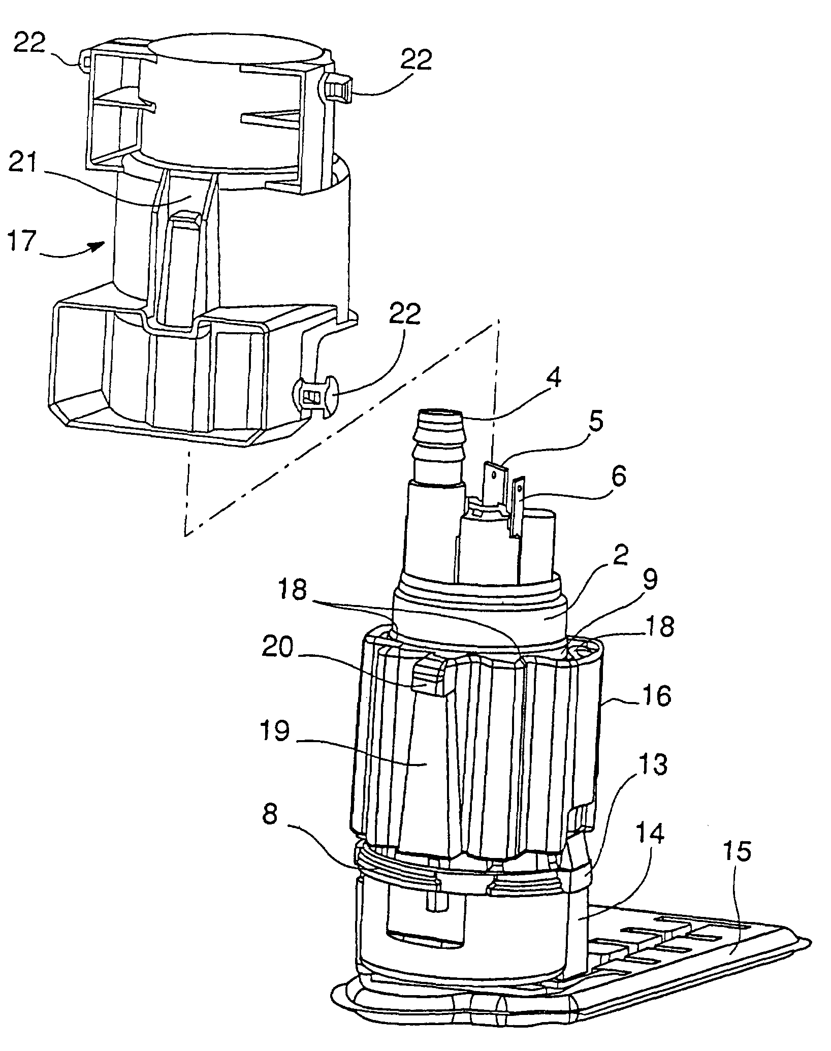
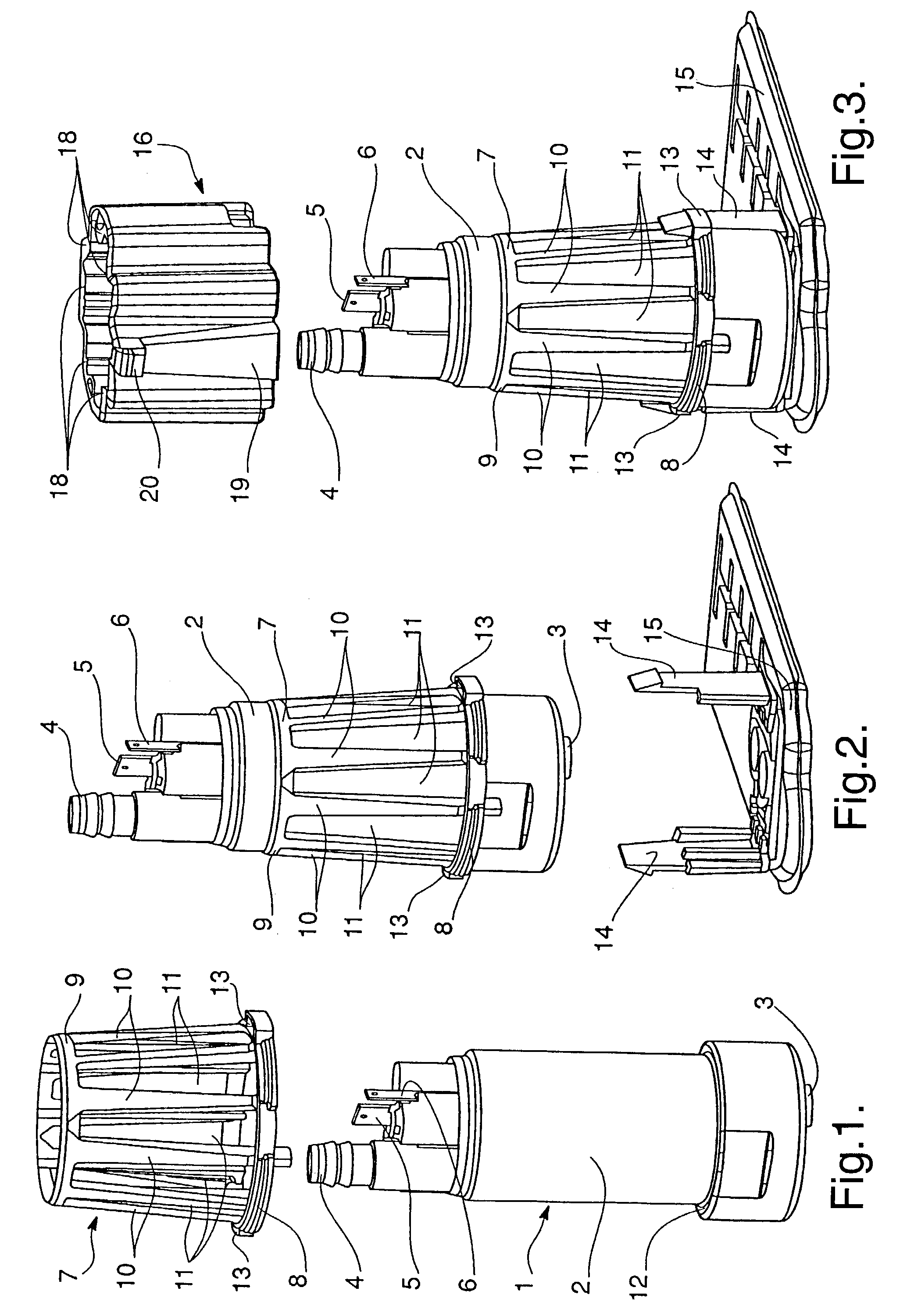
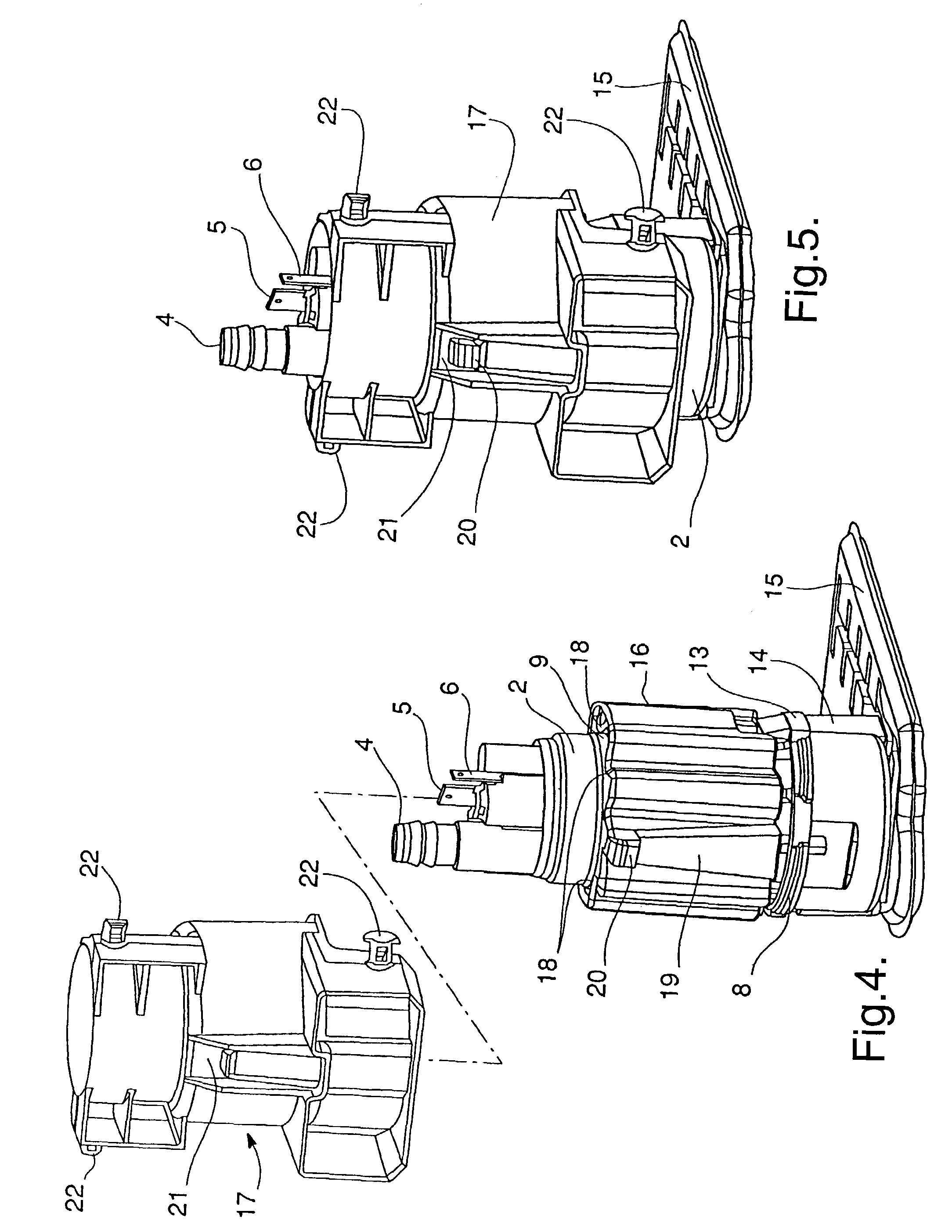
[0033]FIG. 1 shows a pump proper I which will not be described in detail since it is itself well-known to the man skilled in the art. The pump includes a generally cylindrical pump body 2 having at one of its ends an induction orifice 3 and at its opposite end a delivery orifice 4. In the pump body 2 is housed an electric motor (not shown) which is supplied with an electric current through electrical terminals 5, 6 projecting at one of the ends of the pump body 2 and which are connected to a source of electrical energy (not shown).
[0034]On subsequent assembly of the pump from the pumping unit shown in FIG. 1, a cage 7, preferably made of a semi-rigid plastics material, is arrange around the body 2. This cage is formed by a lower ring 8 and an upper ring 9 connected to each other by longitudinal rods 10 uniformly spaced so as to form longitudinal apertures 11, also uniformly spaced, between them...
PUM
 Abstract
Description
Claims
Application Information