Torque transmission device having torque limiter

a transmission device and torque limiter technology, applied in the direction of gearing, couplings, hoisting equipments, etc., can solve the problems of destroying the torque limiter, and so as to avoid erroneous activation of the torque limiter

Inactive Publication Date: 2006-04-11
DENSO CORP
View PDF13 Cites 22 Cited by
  • Summary
  • Abstract
  • Description
  • Claims
  • Application Information

AI Technical Summary

Benefits of technology

[0009]The present invention addresses the above disadvantage. Thus, it is an objective of the present invention to avoid erroneous activation of the torque limiter caused by a weight member connected to a second rotator located on a driven-side.

Problems solved by technology

Thus, when the weight member is installed, and a load, which is induced by vibrations of the weight member, is applied to the torque limiter, a stress of the torque limiter is increased, causing destruction of the torque limiter.
That is, even though the transmitted torque has not reached the predetermined value, the load, which is induced by the vibrations of the weight member, causes erroneous activation of the torque limiter and the destruction of the torque limiter.

Method used


Image

  • Torque transmission device having torque limiter
  • Torque transmission device having torque limiter
  • Torque transmission device having torque limiter

Examples


first embodiment

(First Embodiment)

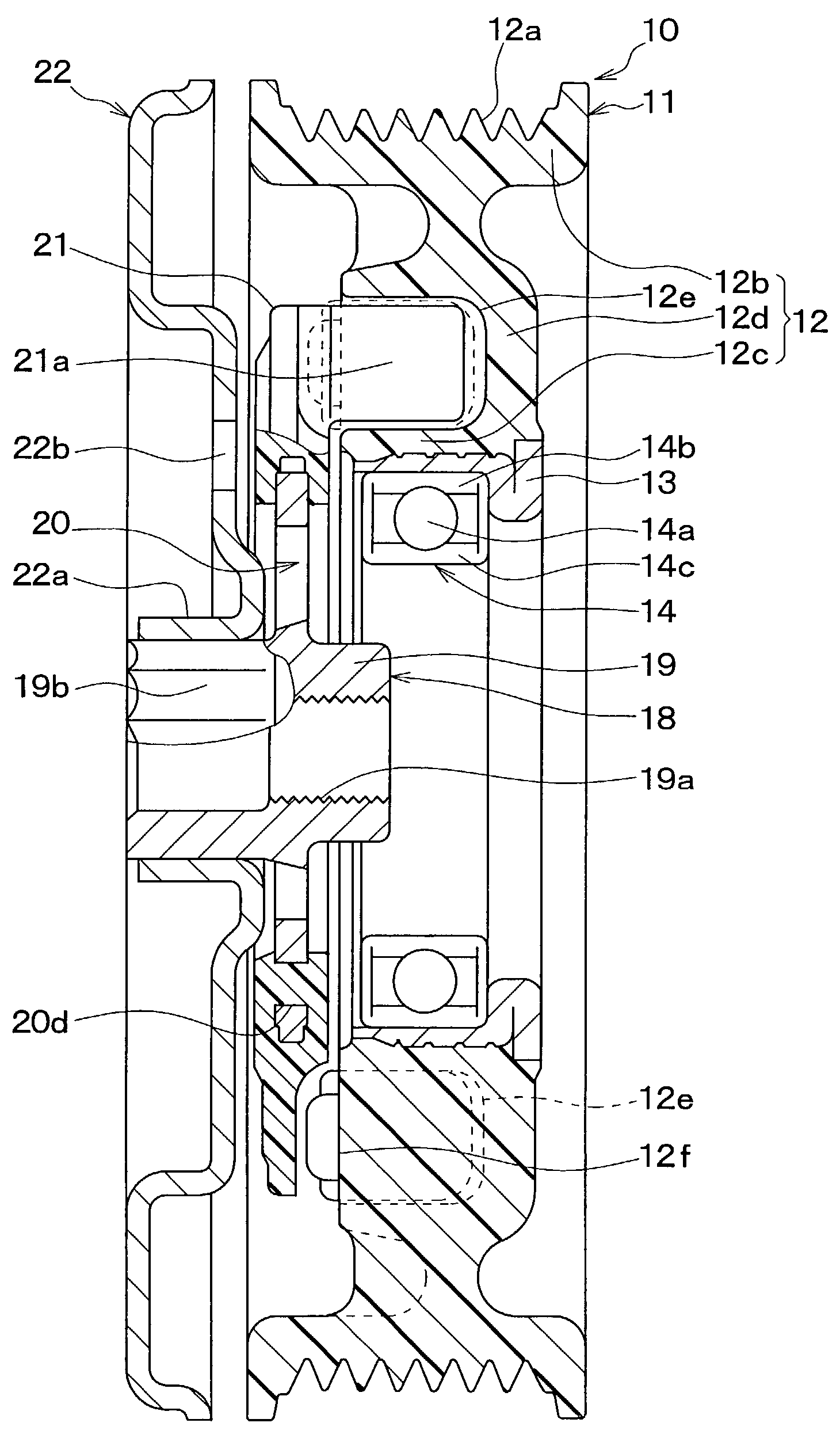
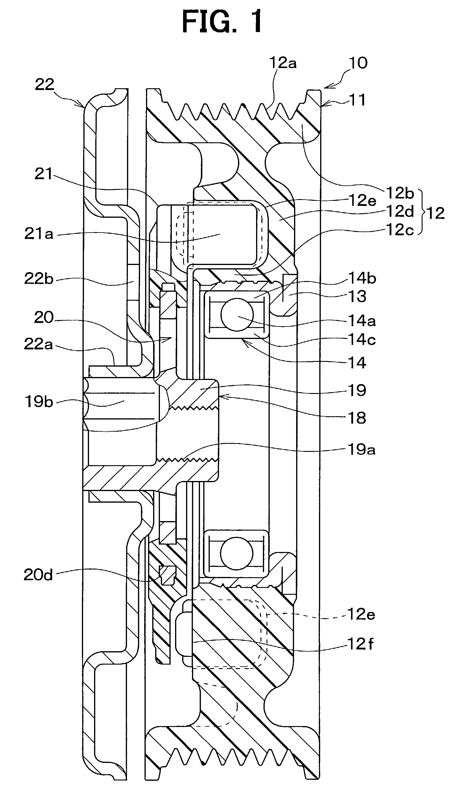
[0035]FIGS. 1 to 9 show a first embodiment of the present invention where the invention is embodied in a torque transmission device, which transmits drive force from a vehicle drive engine to a compressor of a refrigeration cycle of a vehicle air-conditioning system.

[0036]In the torque transmission device 10, a pulley (serving as a first rotator of the present invention) 11 rotates when the pulley 11 receives drive force (torque) from the vehicle drive engine (drive source) through a poly-V belt or multi-V belt (not shown).

[0037]The pulley 11 includes a resin pulley main body 12 and a metal cylindrical member 13. The metal cylindrical member 13 is integrally secured to an inner peripheral section of the pulley main body 12. Specifically, the metal cylindrical member 13 is made of iron metal and is integrally secured to the inner peripheral section of the pulley main body 12 by insert molding at time of molding the pulley main body 12. The pulley main body 12 is pre...

second embodiment

(Second Embodiment)

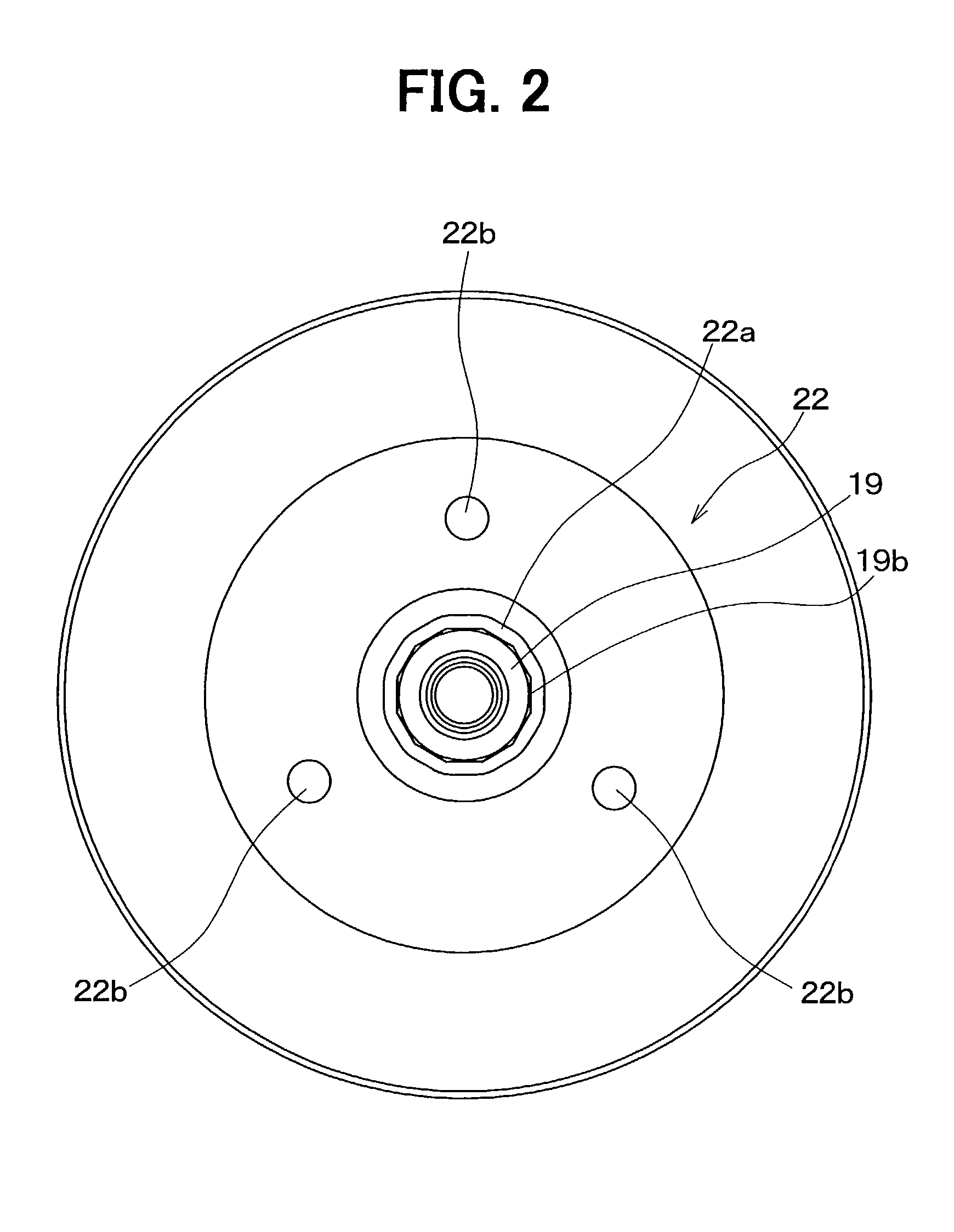
[0069]In the first embodiment, the cylindrical inner peripheral section 22a of the weight member 22 is securely press fitted over the polygonal outer peripheral surface 19b of the inner cylindrical member 19 of the hub member 18. However, in a second embodiment of the present invention, as shown in FIGS. 10 and 11, a male threaded portion 19c is formed in the outer peripheral surface of the inner cylindrical member 19 of the hub member 18 on a side of the inner cylindrical member 19 opposite to the compressor 15. Furthermore, a female threaded portion 22c is formed in the inner peripheral surface of the cylindrical inner peripheral section 22a of the weight member 22. By threadably engaging the female threaded portion 22c with the male threaded portion 19c of the inner cylindrical member 19, the cylindrical inner peripheral section 22a of the weight member 22 is threadably secured to the inner cylindrical member 19 of the hub member 18. Other than those described ...

third embodiment

(Third Embodiment)

[0070]In the second embodiment, the cylindrical inner peripheral section 22a of the weight member 22 is only threadably secured to the inner cylindrical member 19 of the hub member 18. In a third embodiment of the present invention, the cylindrical inner peripheral section 22a of the weight member 22 is more reliably secured to the inner cylindrical member 19 of the hub member 18 through use of threadable engagement and deformation.

[0071]FIGS. 12 to 16 show the third embodiment. Similar to the second embodiment, the male threaded portion 19c is formed in the outer peripheral surface of the inner cylindrical member 19 of the hub member 18, and the female threaded portion 22c is formed in the inner peripheral surface of the cylindrical inner peripheral section 22a of the weight member 22. However, in the third embodiment, besides the male threaded portion 19c, a plurality of recesses 19d (in the present exemplary case, the number of the recesses 19d is three) is form...


PUM


Abstract

A torque transmission device includes a pulley, a cylindrical member, a torque limiter and a weight member. The pulley is rotated by torque transmitted from a drive source. The cylindrical member is connected to a rotatable shaft of a compressor and is rotated integrally with the rotatable shaft. The torque limiter is arranged between the pulley and the cylindrical member and transmits the torque from the pulley to the cylindrical member. The torque limiter disables the transmission of the torque when the torque becomes equal to or greater than a predetermined value. The weight member is secured to the cylindrical member at a point closer to the rotatable shaft than the torque limiter.

Description

CROSS REFERENCE TO RELATED APPLICATION[0001]This application is based on and incorporates herein by reference Japanese Patent Application No. 2001-359587 filed on Nov. 26, 2001.BACKGROUND OF THE INVENTION[0002]1. Field of the Invention[0003]The present invention relates to a torque transmission device, which transmits torque from a drive source, such as an engine, to a driven-side rotating device (auxiliary device), such as a compressor.[0004]2. Description of Related Art[0005]Japanese unexamined patent publication No. 2001-41308, which corresponds to U.S. Pat. No. 6,332,842, discloses a torque transmission device that includes a torque limiter. The torque limiter disables transmission of torque from an engine, which serves as a drive source, to a compressor to prevent generation of an excessively large load in the engine when the transmitted torque becomes equal to or greater than a predetermined value due to, for example, a locked state of the compressor (i.e., a state where the c...

Claims


Application Information

Patent Timeline
Patent Type & Authority Patents(United States)
IPC IPC(8): F16D9/08F16D9/00F16H35/10F16H55/36
CPCF16H55/36F16H35/10Y10T464/50F16F15/10
Inventor TABUCHI, YASUOAGATA, NAOTOSAKAMOTO, HIROYASUOHGUCHI, JUNICHI
Owner DENSO CORP
Why Eureka
Try Eureka