Method for configuring a local positioning system

a local positioning system and local positioning technology, applied in direction finders, direction finders using radio waves, instruments, etc., can solve the problems of inaccurate estimation of the location of an object or a vehicle in a work area, and the local positioning system may not provide accurate measurements of the location of an object or a vehicle, so as to reduce multi-path errors

Active Publication Date: 2006-04-11
DEERE & CO
View PDF36 Cites 48 Cited by
  • Summary
  • Abstract
  • Description
  • Claims
  • Application Information

AI Technical Summary

Benefits of technology

[0003]In accordance with one aspect of the invention, a method for configuring a local positioning system comprises orienting a survey antenna coextensively with a primary beacon associated with a work area. A mobile transmitter or mobile transceiver transmits a first transmission signal from the survey antenna. A receiver or transceiver receives the first transmission at one or more secondary beacons associated with the work area. A data processor determines first elapsed times from the transmission time of the first transmission signal to at least the arrival time at respective corresponding secondary beacons. Each of the first elapsed times falls within a filtering time window or satisfies an edge timing criteria of the coded signal, or both to reduce multi-path error. The first elapsed times are converted into a first position in at least two spatial dimensions for the primary beacon.

Problems solved by technology

The estimated location of an object or vehicle in a work area may be inaccurate because multi-path reflections may be mistaken for direct free-space or line of sight propagation between the wireless devices of a local positioning system.
Further, a local positioning system may not provide accurate measurements of the location of an object or a vehicle, unless the reference locations of the wireless devices are properly determined.

Method used


Image

  • Method for configuring a local positioning system
  • Method for configuring a local positioning system
  • Method for configuring a local positioning system

Examples


Embodiment Construction

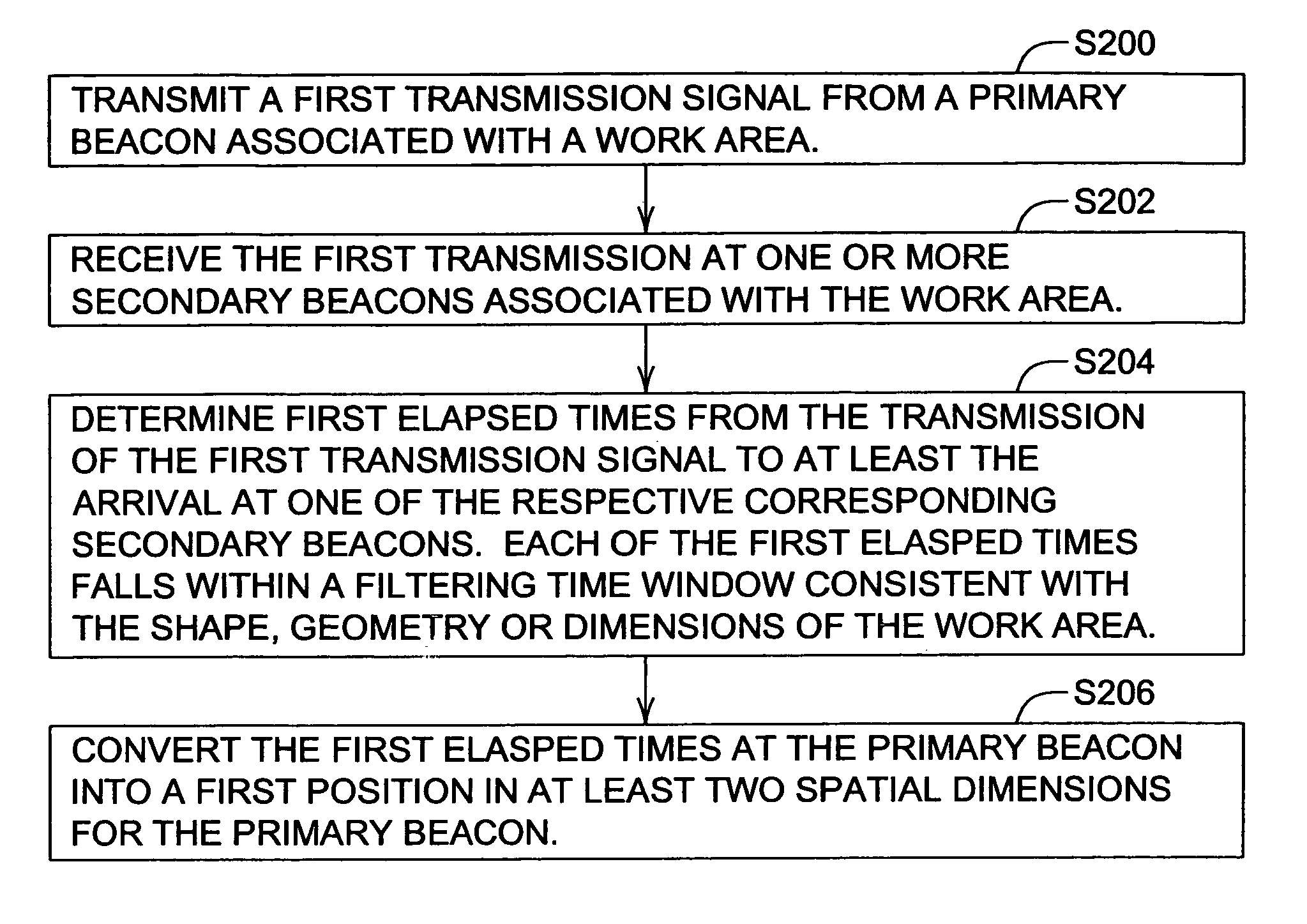
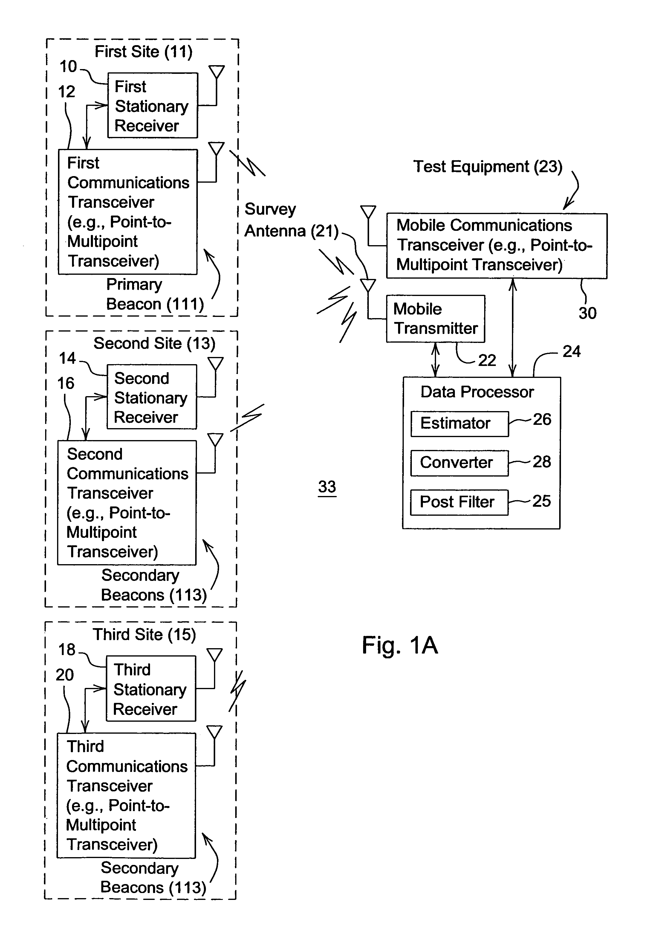
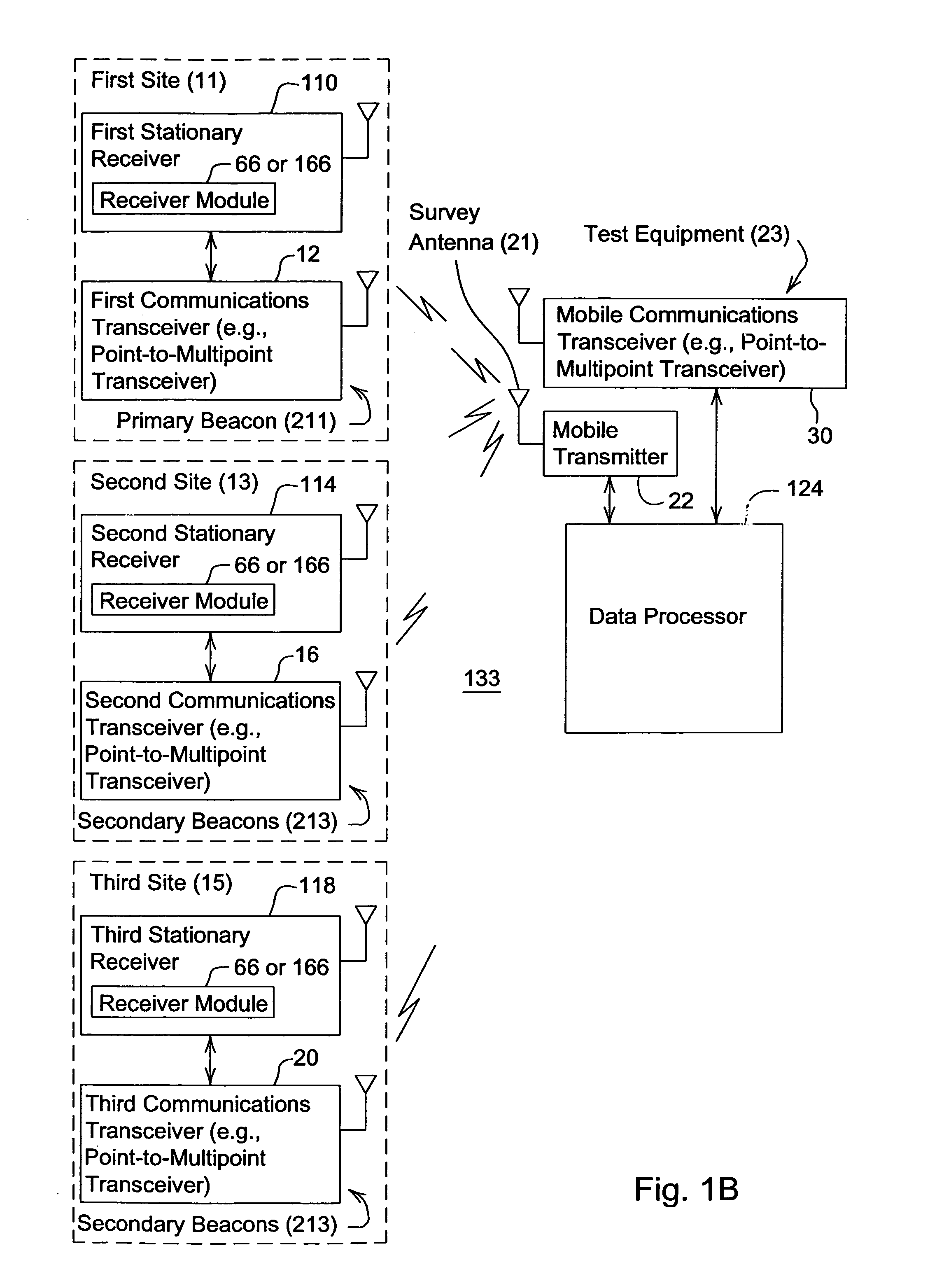
[0024]FIG. 1A illustrates a first embodiment of the local positioning system 33 in a configuration stage. The configuration stage refers to a stage prior to an operational stage in which the local positioning system is used to determine or estimate a location (e.g., geographic coordinates) of a mobile object or a mobile vehicle in the work area. During the configuration stage, the locations (e.g., geographic coordinates) of a group of beacons (111, 113) is determined.

[0025]In accordance with the first embodiment, the local positioning system 33 comprises a primary beacon 111 associated with a first site 11 and second beacons 113 associated with other sites, such as a second site 13 and a third site 15. The primary beacon 111 comprises a first stationary receiver 10 coupled to a first communications transceiver 12. One secondary beacon 113 comprises a combination of a second stationary receiver 14 and a second communications transceiver 16. Another secondary beacon 113 comprises a co...


PUM


Abstract

A method for configuring a local positioning system comprises orienting a survey antenna coextensively with a primary beacon associated with a work area. A transmitter or transceiver transmits a first transmission signal from the survey antenna. A receiver or transceiver receives the first transmission at one or more secondary beacons associated with the work area. A data processor determines first elapsed times from the transmission time of the first transmission signal to at least the arrival time at respective corresponding secondary beacons. Each of the first elapsed times falls within a filtering time window, or satisfies an edge timing criteria of the coded signal, or both to reduce multi-path error. The first elapsed times are converted into a first position in at least two spatial dimensions for the primary beacon.

Description

FIELD OF THE INVENTION[0001]This invention relates to a method for configuring a local positioning system.BACKGROUND OF THE INVENTION[0002]A local positioning system refers to any system that uses terrestrial transmissions of electromagnetic signals (e.g., radio frequency or microwave) to estimate a location of an object or vehicle in a work area. The estimated location of an object or vehicle in a work area may be inaccurate because multi-path reflections may be mistaken for direct free-space or line of sight propagation between the wireless devices of a local positioning system. Further, a local positioning system may not provide accurate measurements of the location of an object or a vehicle, unless the reference locations of the wireless devices are properly determined. Accordingly, there is need to reduce inaccuracies in local positioning systems by reducing the potentially deleterious effects of multi-propagation and deficient installations of wireless devices of the local pos...

Claims


Application Information

Patent Timeline
Patent Type & Authority Patents(United States)
IPC IPC(8): G01S3/02G01S19/22G01S5/02G01S5/14
CPCG01S5/0215H04B1/7073G01S19/22G01S5/14G01S19/11
Inventor HUNT, KENNETH EDWARDSCHMIDT, MARK ALVINHOLM, DAVID ROYSTEPHENS, SCOTT ADAM
Owner DEERE & CO
Why Eureka
Try Eureka