Method for removing noise regions in stereo 3D display system

Active Publication Date: 2006-04-11
SILICON INTEGRATED SYSTEMS
View PDF7 Cites 13 Cited by
  • Summary
  • Abstract
  • Description
  • Claims
  • Application Information

AI Technical Summary

Benefits of technology

[0010]The main object of the present invention is to provide a method for removing a first mask region in the left side of said stereo 3D image and a second mask region in the right side of said stereo 3D image in the stereo 3D system. After considering to the factor of the distance of humans'

Problems solved by technology

Since human beings have two eyes and there is only one monitor,

Method used


Image

  • Method for removing noise regions in stereo 3D display system
  • Method for removing noise regions in stereo 3D display system
  • Method for removing noise regions in stereo 3D display system

Examples


Embodiment Construction

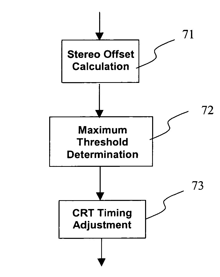
[0024]Due to the process of producing left eye image and right eye image, the image of prior art on the monitor obtains noises regions. The exemplary embodiment below illustrates the method of the present invention of removing noise region in a stereo 3D display system. The present invention removes the noise regions by determining a mask_size and adjusting the CRT timing signals.

[0025]As shown in FIG. 7, in the first step 71, the stereo 3D display system calculates the stereo offset and sets up the initial values such as the distance between the pupil and the midpoint of two eyes and a fusion point etc. The fusion point is used to enhance the stereo effect, especially when most of the objects are located in the distant place that the stereo effect is not obvious. After setting the initial values, in the step 73, the stereo 3D display system calculates a mask_size and adequately adjusts the CRT timing signal to remove the noise region in the step 75.

[0026]FIG. 8 illustrates the calc...


PUM


Abstract

A method for removing noise regions in a stereo 3D image, which includes a first eye image and a second eye image is achieved by calculating a maximum offset value and turning a horizontal synchronization signal and a display enable signal of the CRT timing parameters.

Description

FIELD OF THE INVENTION[0001]The present invention relates to a method for processing a stereo 3D image and more particularly, to a method for removing noise regions of the stereo 3D image in a stereo 3D display system.BACKGROUND OF THE INVENTION[0002]From the 2D plane image and the 3D plane image to the 3D stereo image, the computer user's request for image quality is getting higher and higher. Since human beings have two eyes observing object independently, human beings can see the stereo object. The view angles of two eyes are different so that the images two eyes respectively observe are different. After images fusing by the brain, human beings can see the stereo image. Hereinafter, “stereo” of image means the depth and solidity of the image.[0003]As shown in FIG. 1, in a computer plane 3D graphics system, the AGP or PCI bus 4 transmits the 2D or 3D graphics command to the 3D graphics engine 5. The Digital-Analog Converter 7 displays the analog signal converted from the digital s...

Claims


Application Information

Patent Timeline
IPC IPC(8): G06K9/20H04N13/04H04N13/00
CPCH04N13/0275H04N13/0296H04N13/0051H04N13/0055H04N13/0059H04N13/0285H04N2013/0081H04N13/0431H04N13/0438H04N13/0456H04N13/0497H04N13/167H04N13/189H04N13/194H04N13/275H04N13/286H04N13/296H04N13/334H04N13/341H04N13/361H04N13/398
Inventor LEE, RUEN-RONELU, LI-SHUHUANG, YU-MING
Owner SILICON INTEGRATED SYSTEMS
Why Eureka
Try Eureka