Supercharge Your Innovation With Domain-Expert AI Agents!

Laminated-type high-frequency switch module

a high-frequency switch and laminated technology, applied in the direction of substation equipment, electrical equipment, waveguide devices, etc., can solve the problems of sometimes disconnected mobile phones, increased volume and weight,

Inactive Publication Date: 2006-04-11
HITACHI METALS LTD
View PDF14 Cites 29 Cited by
  • Summary
  • Abstract
  • Description
  • Claims
  • Application Information

AI Technical Summary

Benefits of technology

[0017]The high-frequency amplifier preferably comprises an amplifier circuit having a transistor, an input-matching circuit connected to the input side of the amplifier circuit, an output-matching circuit connected to the output side of the amplifier circuit, each of the input-matching circuit and the output-matching circuit comprising a capacitor and an inductor, the tran

Problems solved by technology

According to recent rapid expansion of mobile phones, however, a frequency band allocated, to each system cannot allow all users to use their mobile phones in major cities in advanced countries, resulting in difficulty in connection and thus causing such a problem that mobile phones are sometimes disconnected during communication.
Accordingly, the mobile phone is not only expensive, but it also has increased volume and weight, whereby it is not suitable for mobile gears.
Because these discrete parts are mounted onto the circuit board, the multiband mobile phones have large transmission parts, resulting in large overall size.
In addition, because discrete parts are connected with lines on a circuit board, the characteristics of the transmission parts are deteriorated by the loss of the connecting lines.
Further, serious problems with multiband mobile phones that should be miniaturized are increase in mounting areas because of the increased number of parts, the addition of parts such as capacitors, inductors, etc. for impedance matching between the parts, increase in insertion loss, etc.

Method used


Image

  • Laminated-type high-frequency switch module
  • Laminated-type high-frequency switch module
  • Laminated-type high-frequency switch module

Examples


embodiments

[3] Embodiments

(1) First Embodiment

[0086]FIG. 7 is a plan view showing the laminate-type, high-frequency switch module according to one embodiment of the present invention, FIG. 8 is a perspective view showing a laminate portion thereof, and FIG. 9 is an exploded view showing the inner structure thereof. In this embodiment, distributed constant lines for the first and second filter circuits, the low-pass filter circuit and the switch circuits, and distributed constant lines for the directional coupling circuits are formed in the laminate, while diodes and high-capacitance capacitors as chip capacitors, which cannot be formed in the laminate, are mounted onto the laminate surface, resulting in a one-chip, laminate-type, high-frequency switch module.

[0087]This laminate can be produced by preparing green sheets of 20–200 μm in thickness from low-temperature-sinterable dielectric ceramics; printing an electrically conductive, Ag-based paste onto each green sheet to form a desired electr...

second embodiment

(2) Second Embodiment

[0108]This embodiment relates to a triple-band, laminate-type, high-frequency switch module. FIG. 18 is a circuit block diagram showing the laminate-type, high-frequency switch module of the present invention, and FIG. 19 is a view showing one example of its equivalent circuit.

[0109]The first and second filter circuits and the first switch circuit SW1 for the first transmitting / receiving system (GSM) are the same as those in the first embodiment in terms of an equivalent circuit. The second switch circuit SW2 comprises one switch circuit SW2-1 for switching a reception circuit RX2 of the second transmitting / receiving system (DCS1800) and a reception circuit RX3 of the third transmitting / receiving system (PCS), and another switch circuit SW2-2 for switching a transmission circuit TX2 of DCS / PCS and a switch circuit SW2-1.

[0110]The switch circuit SW2-1 for switching the reception circuit RX2 of DCS and the reception circuit RX3 of PCS comprises two diodes DP3, DP4...

third embodiment

(3) Third Embodiment

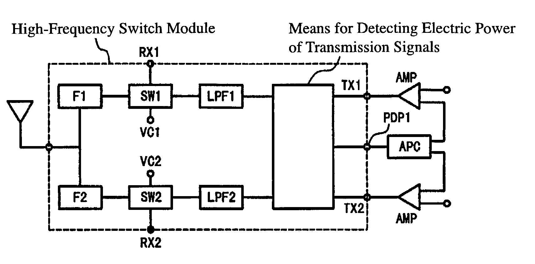
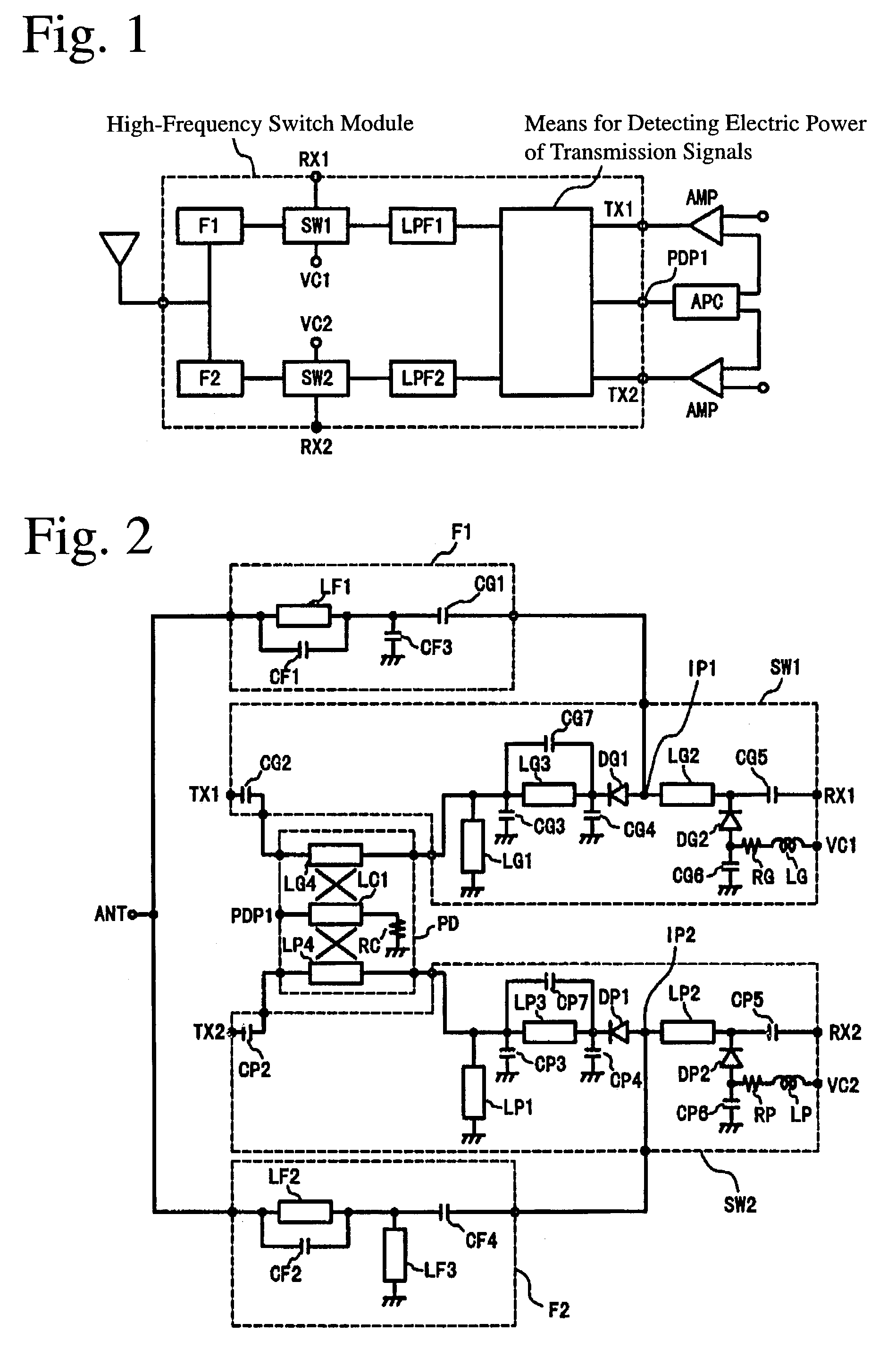
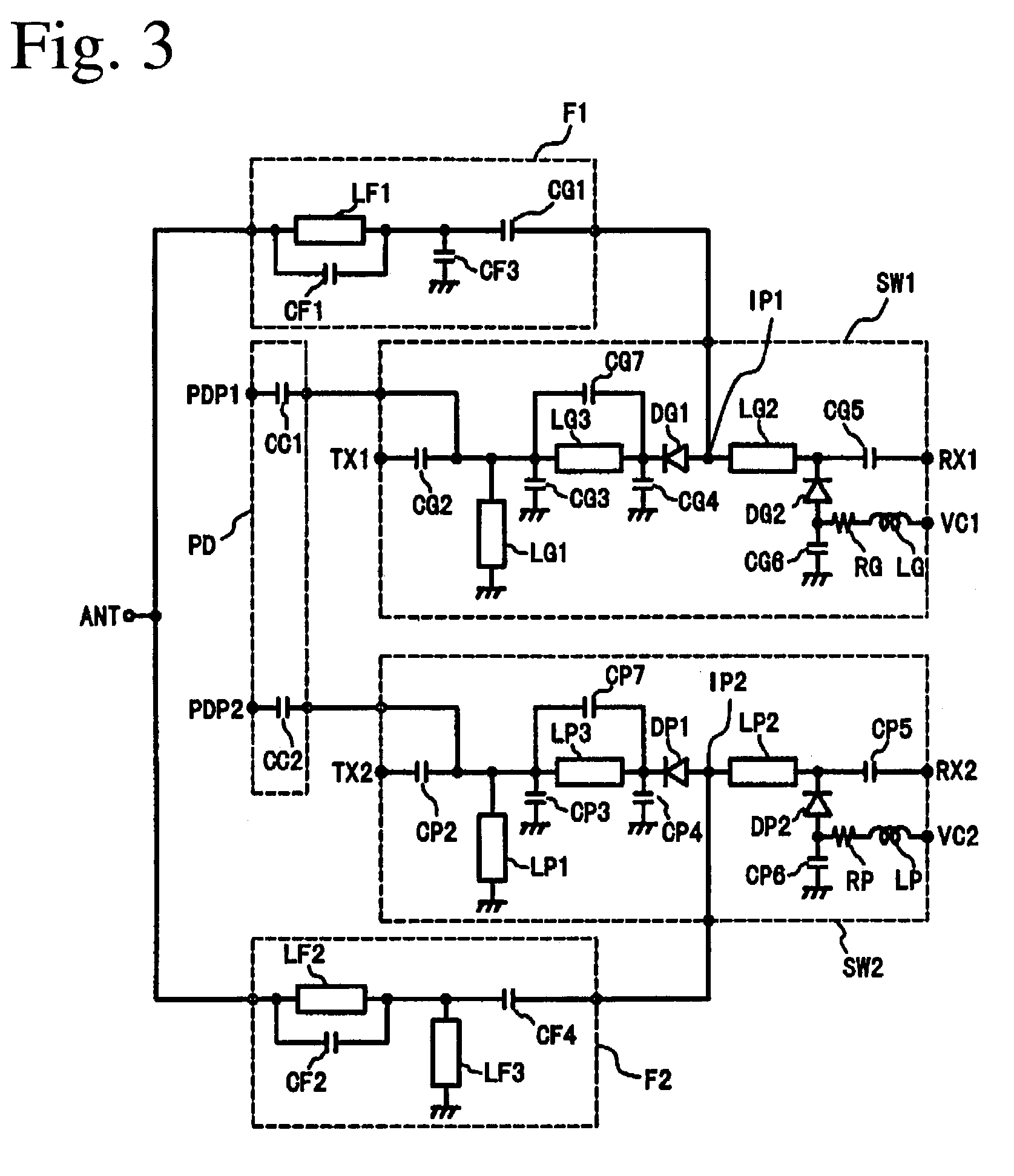
[0114]As shown in FIG. 20, the laminate-type, high-frequency switch module of this embodiment comprises, downstream of the antenna, a high-frequency switch (SPDT switch) SW for switching a transmission signal line and a reception signal line of two transmitting / receiving systems. It comprises two branching circuits downstream of the high-frequency switch SW, one branching circuit DIP1 being connected to the two transmitting systems TX1, TX2 to synthesize a transmission signal. The term “synthesize a transmission signal” used herein means that a transmission signal sent from one operating transmitting system among a plurality of transmitting systems TX1, TX2 is permitted to pass. Also, the other branching circuit DIP2 is connected to the two receiving systems RX1, RX2 to branch a reception signal. This laminate-type, high-frequency switch module also comprises a means PD for detecting the electric power of transmission signals sent from the transmission circuits T...


PUM


Abstract

A laminated high-frequency switch module for selecting either a transmission circuit or a reception circuit of each of transmission / reception systems by switching, comprising a demultiplexer for demultiplexing signals of the transmission / reception systems, high-frequency switch circuits for selecting either the signal path of a reception signal from the demultiplexer to the reception circuit or the signal path of a transmission signal from the transmission circuit to the demultiplexer, and circuit for measuring the power of the transmission signal from the transmission circuit, characterized in that the laminate is composed of dielectric layers having electrode patterns, and the demultiplexer, the high-frequency switch circuits, and the power measuring circuit are constituted of electrode patterns in the laminate.

Description

FIELD OF THE INVENTION[0001]The present invention relates to a laminate-type, high-frequency switch module used in high-frequency bands such as microwave bands, for controlling signal lines between an antenna and transmission circuits and reception circuits in a plurality of transmitting / receiving systems, particularly to a laminate-type, high-frequency switch module having a function to detect the electric power of a transmission signal supplied from each transmission circuit.BACKGROUND OF THE INVENTION[0002]Wireless communications devices, for instance, mobile phones, have become popular remarkably in recent years with their functions and services improved increasingly. Explanation will be made on a mobile phone as an example. There are various systems for mobile phones, for instance, GSM (global system for mobile communications) and DCS1800 (digital cellular system 1800) systems widely used mostly in Europe, a PCS (personal communications services) system used in the U.S., and a ...

Claims


Application Information

Patent Timeline
IPC IPC(8): H04B1/44H04B1/48
CPCH04B1/48H04B1/44
Inventor TAI, HIROYUKIKEMMOCHI, SHIGERUWATANABE, MITSUHIRO
Owner HITACHI METALS LTD
Features
  • R&D
  • Intellectual Property
  • Life Sciences
  • Materials
  • Tech Scout
  • Unparalleled Data Quality
  • Higher Quality Content
  • 60% Fewer Hallucinations
Learn More