Fluid heat exchange control system

a control system and fluid technology, applied in the direction of fluid pressure control, domestic cooling apparatus, heating types, etc., can solve the problems of additional equipment and maintenance costs, and the hydronic system often suffers from a number of deficiencies

Active Publication Date: 2006-04-18
ITT MFG ENTERPRISES LLC
View PDF44 Cites 47 Cited by
  • Summary
  • Abstract
  • Description
  • Claims
  • Application Information

AI Technical Summary

Problems solved by technology

However, such hydronic systems often suffer from a number of deficiencies.
However, the inclusion of this equipment results in additional equipment and maintenance costs.

Method used


Image

  • Fluid heat exchange control system
  • Fluid heat exchange control system
  • Fluid heat exchange control system

Examples


Embodiment Construction

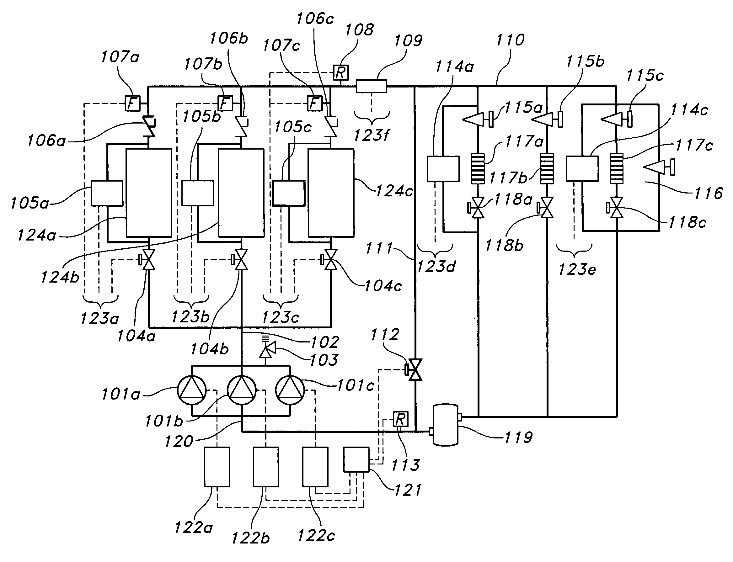
[0012]Preferred features of selected embodiments of this invention will now be described with reference to the figures. It will be appreciated that the spirit and scope of the invention is not limited to the embodiments selected for illustration. Also, it should be noted that the drawings are not rendered to any particular scale or proportion. It is contemplated that any of the configurations and materials described hereafter can be modified within the scope of this invention.

[0013]As described herein, fluid heat exchange units are provided to heat or cool a fluid. For example, chillers and boilers are exemplary types of fluid heat exchange units. In certain exemplary embodiments of the present invention (as described herein), a load fed by the fluid heat exchange units includes fluid to air heat exchange units (i.e., air handling units), whereby air used to heat or cool an area is heated or cooled using fluid from one or more fluid heat exchange units (e.g., chillers).

[0014]FIG. 1 ...


PUM


Abstract

A method of controlling a hydronic system is provided. The hydronic system includes a plurality of fluid heat exchange units for feeding a load, and a bypass valve for bypassing the load. The method includes operating at least a first and a second fluid heat exchange unit in the hydronic system to heat or cool a fluid. An output fluid flow of each of the operating fluid heat exchange units is monitored. The monitored output fluid flow of each fluid heat exchange unit is compared to a predetermined fluid flow setpoint. The output fluid flow of each of the operating fluid heat exchange units is adjusted towards the predetermined fluid flow setpoint if the monitored output flow is different from the predetermined fluid flow setpoint by at least a predetermined margin. A combined output fluid flow of the operating fluid heat exchange units is also monitored. The bypass valve is at least partially opened if the combined output fluid flow is below a predetermined minimum combined output fluid flow. A previously idle fluid heat exchange unit is operated if the combined output fluid flow is greater than a predetermined maximum combined output fluid flow for the number of operating fluid heat exchange units.

Description

FIELD OF THE INVENTION[0001]This invention relates to a control system for controlling a fluid heat exchange system, and more particularly, to a control system for controlling a fluid heat exchange system based upon predetermined criteria.BACKGROUND OF THE INVENTION[0002]In existing hydronic systems it is often desirable to provide a number of pieces of equipment of the same type, or of a similar type. For example, such equipment may include water pumps, water chillers, and associated heat exchange units. By supplying a hydronic system with such repetitive or redundant equipment, a system capable of providing for varying demand, or for accommodating for maintenance of the equipment, is provided.[0003]However, such hydronic systems often suffer from a number of deficiencies. For example, such systems may include equipment such as decoupling piping and distribution flow loop pumps. These pieces of equipment are typically utilized in order to provide for isolation, and to provide an ap...

Claims


Application Information

Patent Timeline
Patent Type & Authority Patents(United States)
IPC IPC(8): F25D17/02F24F3/06
CPCF24F3/06F25D17/02
Inventor ALER, MARK DENNISGU, JAMES JIN-HAOSANCHEZ, KAREN JO
Owner ITT MFG ENTERPRISES LLC
Why Eureka
Try Eureka