Moving object with fuel cells incorporated therein and method of controlling the same

a technology of moving objects and fuel cells, which is applied in the direction of gas pressure propulsion mounting, process and machine control, propulsion parts, etc., can solve the problems of fuel cells, insufficient discussion on the optimum combination, and inability to recover power generation ability, so as to save fuel and improve the driving efficiency of heat engines.

Inactive Publication Date: 2006-04-18
TOYOTA JIDOSHA KK
View PDF29 Cites 71 Cited by
  • Summary
  • Abstract
  • Description
  • Claims
  • Application Information

AI Technical Summary

Benefits of technology

[0018]One object of the present invention is thus to provide a moving object with fuel cells mounted thereon, which effectively uses the fuel cells as an energy output source and has excellent fuel consumption and environmental properties.
[0019]Another object of the present invention is to provide a simple structure that effectively prevents confusion between a plurality of fuels supplied.
[0020]Still another object of the present invention is to provide a technique that efficiently controls a variation in torque output from a heat engine with a torque of a motor.

Problems solved by technology

There is accordingly no sufficient discussion on the optimum combination of the output characteristics of the fuel cells with those of another energy output sources such as a heat engine.
The fuel cells, on the other hand, do not recover their power generation ability without an external supply of fuel.
Another disadvantage of the fuel cells is a poor response.
In the proposed hybrid vehicles with the fuel cells, however, the effective use of the fuel cells has not been fully considered by taking into account the above characteristics.
In the proposed hybrid vehicles with the fuel cells mounted thereon, the fuel cells are used only in a limited manner and not fully utilized.
The fuel cells accordingly have a poor response to a requirement of power generation.
There has been no sufficient discussion on the method of compensating for the poor response and outputting the required electric power.
No simple structure, however, has been proposed to prevent confusion between the plurality of fuels supplied.
The conventional vehicles have another problem relating to vibration damping of the engine as discussed below.
There has been no sufficient discussion on the effective use of the fuel cells as the electric power supply of the motor in the torque control.
The torque control technique with the secondary battery, however, has a problem that the extraction and supply of electric power from and into the motor are difficult to balance, and thereby the electric power of the secondary battery is often consumed excessively.
This is ascribed to a conversion loss between the mechanical power and the electric power due to the charge and discharge efficiencies of the secondary battery.
While the motor carries out power operation for the vibration damping, this proposed technique restricts the discharge of the secondary battery by the amount of the electric power previously regenerated and causes the fuel cells to compensate for an insufficiency of electric power.
The electric power supplied from the secondary battery, however, has a low efficiency due to the losses in the charging and discharging process.
The primary use of such electric power results in lowering the energy efficiency in the vibration damping.
The use of the fuel cells for the purpose of compensation does not effectively draw the advantages of the fuel cells having the high efficiency of power generation.
The issues discussed above arise not only in the hybrid vehicles but in any moving objects having a plurality of energy output sources including fuel cells.

Method used


Image

  • Moving object with fuel cells incorporated therein and method of controlling the same
  • Moving object with fuel cells incorporated therein and method of controlling the same
  • Moving object with fuel cells incorporated therein and method of controlling the same

Examples


second embodiment

F. Second Embodiment

[0475]The following describes another hybrid vehicle in a second embodiment according to the present invention. The first embodiment and its modified examples regard the hybrid vehicle that is driven with the power output to only one axle. The technique of the first embodiment is, however, not restricted to this structure, but is applicable to a hybrid vehicle that is driven with the power output to two axles, that is, a four wheel-drive hybrid vehicle. The application to the four wheel-drive hybrid vehicle is described below as the second embodiment.

[0476]FIG. 20 schematically illustrates the structure of the hybrid vehicle in the second embodiment. The difference from the first embodiment is that power may be output to two axles 17 and 17A in the hybrid vehicle of the second embodiment. The structure of the second embodiment enables the driver to arbitrarily set the output of power to the axle 17A. A 4WD mode switch for specifying the four-wheel drive is dispos...

third embodiment

G. Third Embodiment

[0491]The following describes still another hybrid vehicle in a third embodiment according to the present invention. FIG. 22 schematically illustrates the structure of the hybrid vehicle in the third embodiment.

[0492]The difference between the third embodiment and the first embodiment is the mechanism of transmitting power of the engine 10 and a motor 20B to the axle 17. In the structure of the third embodiment, the transmission mechanism has a continuously variable transmission 180 (hereinafter referred to as CVT) and a sub-transmission 170, which is disposed before the CVT 180 to change the speed of the power transmitted to the CVT 180.

[0493]The CVT 180 is a known mechanism, in which two pairs of pulleys 181a,181b and 182a,182b are arranged to make rotating shafts parallel to each other, and the power is transmitted between the two pairs of pulleys 181a,181b and 182a,182b via a belt 183. The interval between the paired pulleys 181a and 181b or 182a and 182b is v...

fourth embodiment

H. Fourth Embodiment

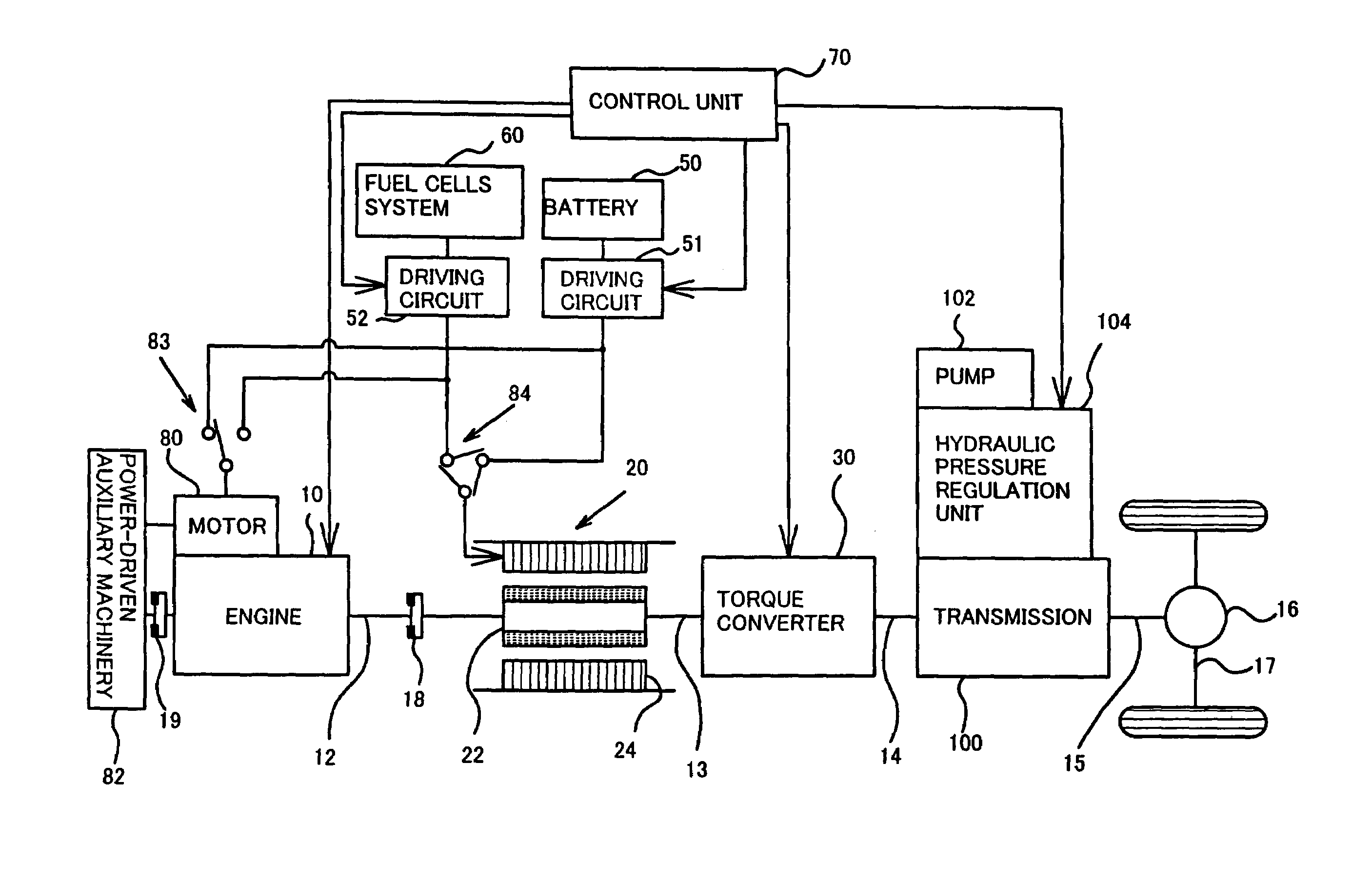
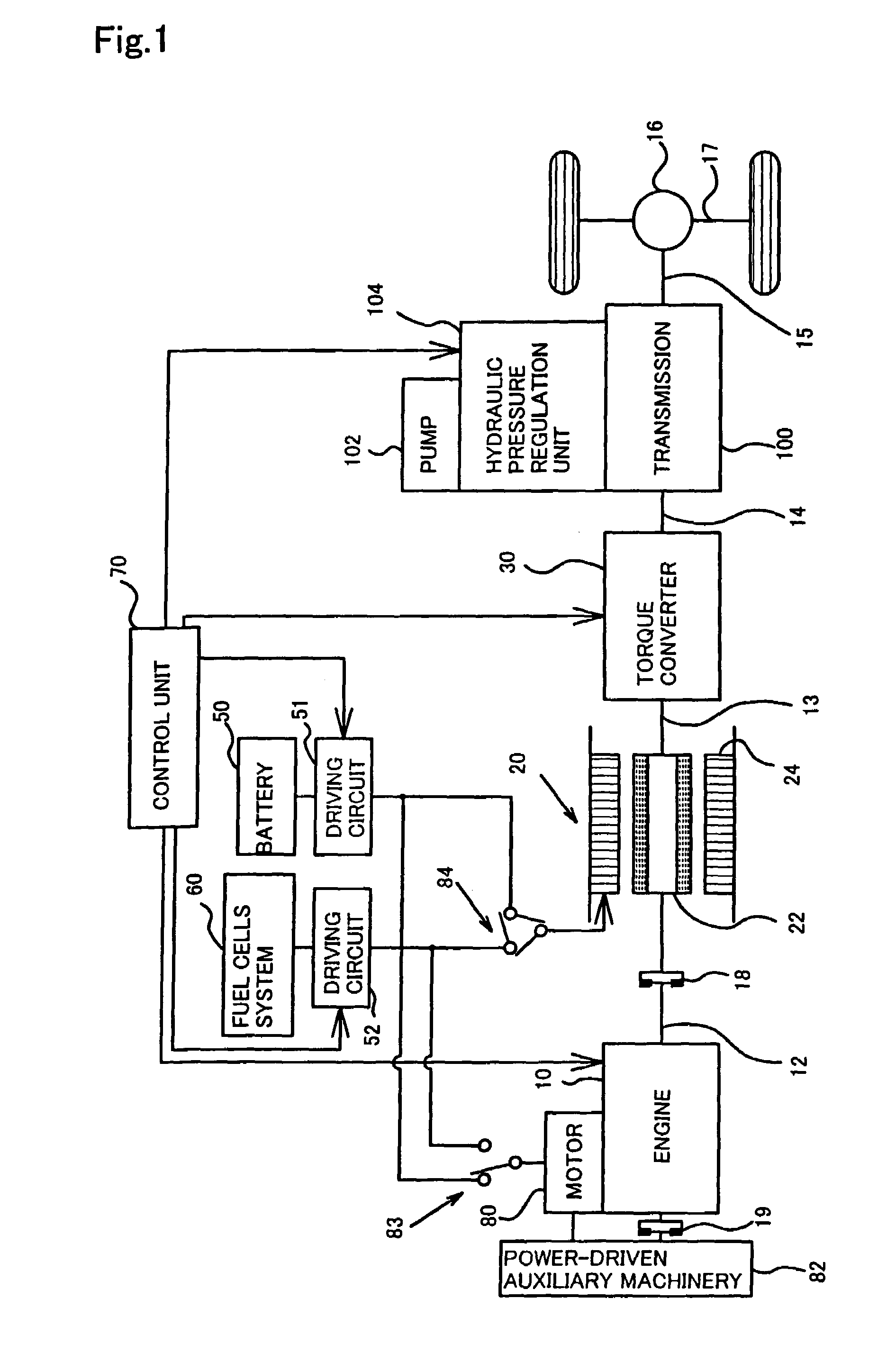
[0522]The following describes a fourth embodiment according to the present invention. The hybrid vehicle of the fourth embodiment has the same hardware structure as that of the hybrid vehicle of the first embodiment shown in FIG. 1. The basic operations of the fourth embodiment are also identical with those of the first embodiment. The hybrid vehicle of the fourth embodiment is driven by properly using the engine 10 and the motor 20 according to the maps of FIGS. 8 through 11. The motor 20 is driven with the electric power output from the fuel cell 60. The technique of the first embodiment controls the operation of the motor 20 according to the remaining quantity of the FC fuel. The technique of the fourth embodiment, on the other hand, controls the operation of the engine 10 according to the remaining quantity of the fuel for the engine 10, that is, the remaining quantity of gasoline.

[0523]FIG. 33 is a flowchart showing a drive control routine executed in the fo...


PUM

PropertyMeasurementUnit
electric poweraaaaaaaaaa
total poweraaaaaaaaaa
speedaaaaaaaaaa

Abstract

In a hybrid vehicle with fuel cells and an engine mounted thereon as energy output sources, the technique of the present invention adequately changes a working energy output source according to a driving state of the hybrid vehicle. The hybrid vehicle has the engine and a motor, both enabling power to be output to an axle. The hybrid vehicle also has fuel cells as a main electric power supply for driving the motor. The technique of the present invention changes the working energy output source between the fuel cells and the engine, in order to reduce the output of the fuel cells with consumption of a fuel for the fuel cells. With a decrease in remaining quantity of the fuel, the technique narrows a specific driving range, in which the motor is used as the power source. The technique also causes the engine to drive the motor as a generator and charges a battery not with electric power of the fuel cells but with electric power generated by the motor. This arrangement effectively prevents the fuel for the fuel cells from being excessively consumed in one driving mode. The fuel cells can thus be used preferentially in a specific driving state of the hybrid vehicle where the fuel cells have a high efficiency.

Description

CROSS REFERENCE TO RELATED APPLICATION[0001]This application is a divisional application of, and claims priority to, Ser. No. 09 / 576,444, filed on May 22, 2000, now U.S. Pat. No.6,672,415.BACKGROUND OF THE INVENTION[0002]1. Field of the Invention[0003]The present invention relates to a moving object with at least two energy output sources including fuel cells incorporated therein, a driving apparatus for the moving object, and a method of controlling the moving object.[0004]2. Description of the Related Art[0005]Hybrid vehicles with an engine and a motor mounted thereon have been proposed recently. In one form of the hybrid vehicle called a parallel hybrid vehicle, the power of both the motor and the engine is output to a drive shaft. The parallel hybrid vehicle has the engine and a battery as energy output sources to produce mechanical and electrical power to rotate the drive shaft. The parallel hybrid vehicle may run only with the power from the engine or from the battery. Proper ...

Claims


Application Information

Patent Timeline
Patent Type & Authority Patents(United States)
IPC IPC(8): B60K1/00B60K6/365B60K6/48B60K6/52B60K6/543B60K6/547B60K15/04B60L11/18B60W10/02B60W10/06B60W10/08B60W10/10B60W10/26B60W10/28B60W10/30B60W20/00F16H3/66H01M8/00H01M16/00
CPCB60K6/365B60W20/10B60K6/52B60K6/543B60K6/547B60K15/04B60L11/1881B60L11/1892B60L11/1894B60W10/02B60W10/06B60W10/08B60W10/10B60W10/26B60W10/28B60W10/30B60W20/00H01M16/006B60K6/48B60K2001/005B60W2510/244F16H3/66F16H2200/0047F16H2200/2012H01M8/00Y02T10/6221Y02T10/6265Y02T10/6269Y02T10/6286Y02T90/34Y10S903/945Y10S903/946Y10S903/91Y10S903/916Y10S903/919Y10S903/918Y10S903/944B60W2710/105B60W2560/02B60L58/30B60L58/33B60L58/34B60W2530/209Y10S903/908Y02T10/62Y02T90/40Y02E60/50Y02E60/10B60K6/32B60W20/40B60W2510/105B60W2510/28B60W2710/28
Inventor TABATA, ATSUSHI
Owner TOYOTA JIDOSHA KK
Why Eureka
Try Eureka