Shield and connector with the shield

a shield and connector technology, applied in the direction of shield and shield arrangement, coupling device connection, electrical equipment, etc., can solve the problems of serious damage to the integrity of the shield, inability to achieve reliable insertion between the male and female connectors, and difficulty in achieving steady propping between the two shields, so as to reduce electromagnetic interference of the connector, reliable and steady propping function, reliable and steady insertion function

Inactive Publication Date: 2006-04-18
CHENG UEI PRECISION IND CO LTD
View PDF13 Cites 29 Cited by
  • Summary
  • Abstract
  • Description
  • Claims
  • Application Information

AI Technical Summary

Benefits of technology

[0007]An object of the invention is to provide a shield for reducing electromagnetic interference of connectors. The shield comprises a top surface, a bottom surface and two lateral surfaces to provide an insertion room in which a connector is received. A plurality of first cantilever elastic slices is formed at the top and lateral surfaces of the shield. A second cantilever elastic slice is formed at the top surface of the shield. The second cantilever elastic slice is arranged between the first cantilever elastic slices at the top surface of the shield. A pair of slots is formed on the second cantilever elastic slice. A simple supporting beam is formed between the two slots. The simple supporting beam projects and props a shield of a mated connector. The shield achieves an integral and continuous shielding function, a reliable and steady propping function between the shield and the mated connector.
[0008]Another object of the invention is to provide a connector with the shield. According to the present invention, the connector includes a plastic casing which inserts into the shield and receives a plurality of contacts. The connector with the shield achieves an integral and continuous electromagnetic shielding function and a reliable and steady insertion function between the connector and the mated connector.
[0009]According to the invention, the simple supporting beam tightly props the shield of the mated connector. The second cantilever elastic slice has well elasticity and automatically adjusts the propping force between the simple supporting beam and the shield, so that the simple supporting beam always credibly and steadily props the shield without damage of the shield. Then, a reliable insertion and cooperation function between the two connectors is achieved. An indeed communication and grounding function between the two shields is achieved too. The first cantilever elastic slices and second cantilever elastic slice are all set in the front of the shield. There is no large hollow area formed at the surface of the shield. So that the integrality of the shield is not damaged, the integral and continuous shielding function of the shield is achieved.

Problems solved by technology

The rigidity of the cantilever elastic slice is weaker, so that it is difficulty to achieve a steady propping function between the two shields.
It is impossible to achieve the reliable insertion between the male and female connectors, the indeed communication and grounding between the two shields.
But large hollow area is formed at each surface of the shield; the integrity of the shield is seriously damaged.
Then the integrity and continuity of the shielding is difficulty to achieved.

Method used


Image

  • Shield and connector with the shield
  • Shield and connector with the shield
  • Shield and connector with the shield

Examples


Embodiment Construction

[0013]The present invention will now be described with respect to the accompanying drawings in which like numbered elements represent like parts.

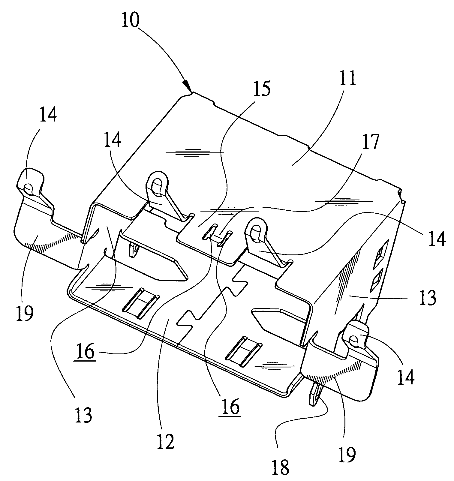
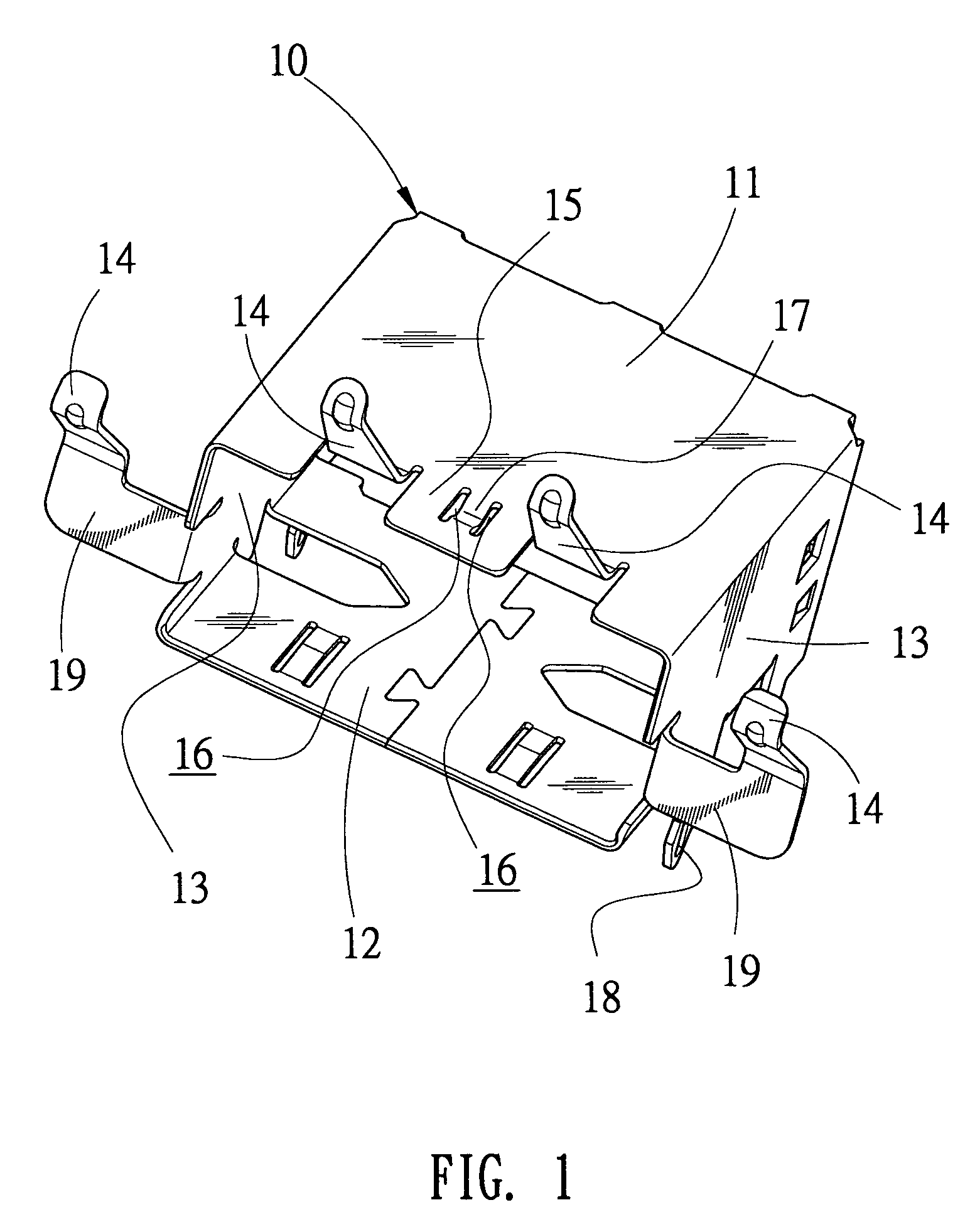
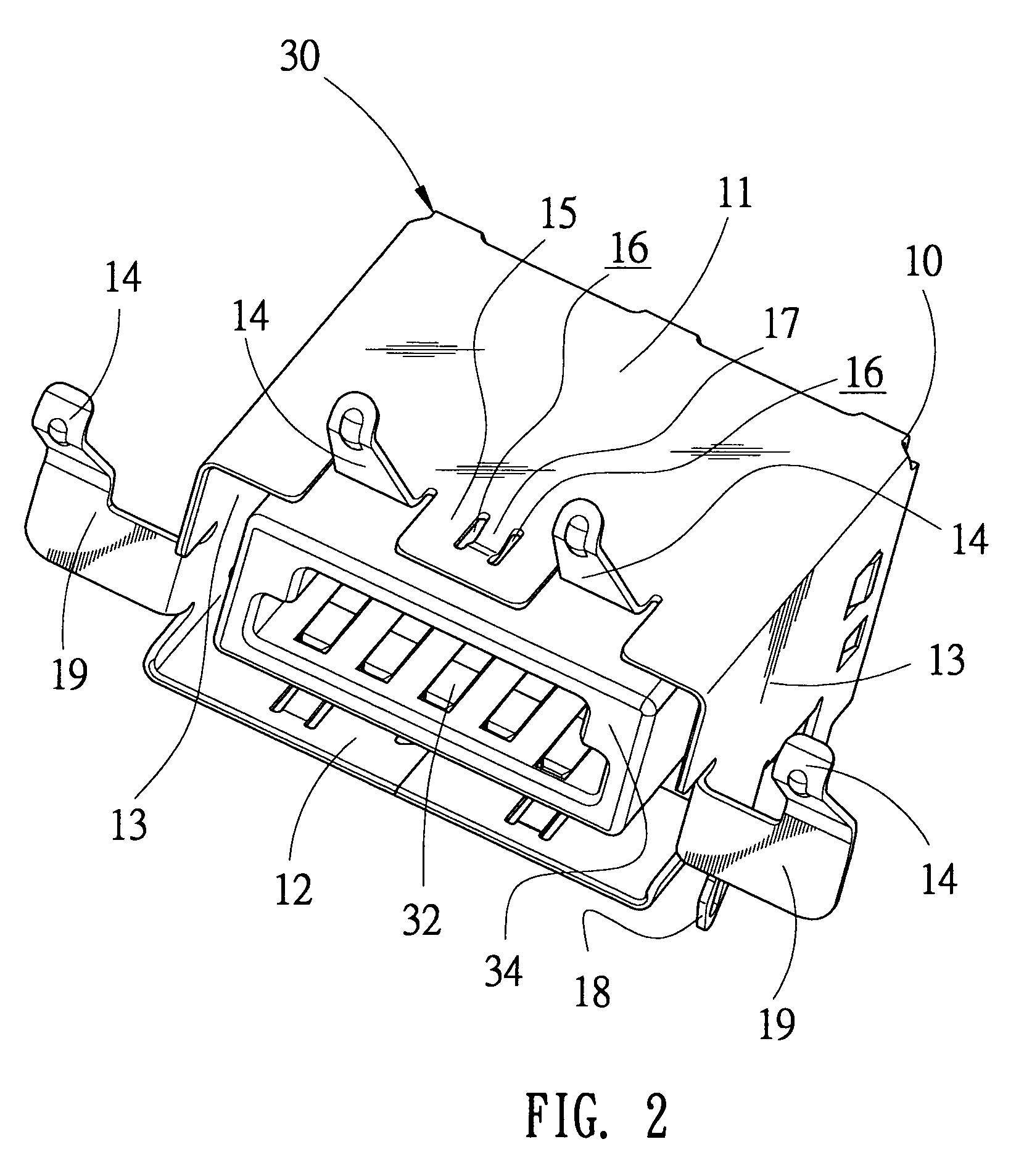
[0014]With reference to FIGS. 1 and 3, a shield 10 of the present invention is a rectangular block section in which a connector 30 is received. The shield 10 comprises a top surface 11, a bottom surface 12 and two lateral surfaces 13. The surfaces 11, 12 and 13 and the connector 30 provide an insertion room into which a shield 80 of a connector 90 inserts.

[0015]There are a plurality of first cantilever elastic slices 14 formed at the top and lateral surfaces of the shield 10. A second cantilever elastic slice 15 is formed at the top surface of the shield 10. The second cantilever elastic slice 15 is arranged between the first cantilever elastic slices 14 at the top surface of the shield 10. The second cantilever elastic slice 15 is longitudinally incised to form two slots 16. A simple supporting beam 17 is formed between the two slots 16. T...


PUM


Abstract

The present invention provides a shield and a connector with the shield. The shield includes a top surface, a bottom surface and two lateral surfaces to receive the connector. A plurality of first cantilever elastic slices is formed at the top and lateral surfaces of the shield. A second cantilever elastic slice is formed at the top surface of the shield. The second cantilever elastic slice is longitudinally incised to form two slots. A simple supporting beam is formed between the two slots. The simple supporting beam projects and props a mated connector. The received connector further includes a plastic casing. The plastic casing inserts into the shield and receives a plurality of contacts. So that the reliable and steady insertion function between the shield and the connector is obtained, the integral and continuous shielding function of the shield is achieved too.

Description

BACKGROUND OF THE INVENTION[0001]1. Field of the Invention[0002]The present invention relates to a shield and a connector with the shield, and more especially to a shield and a connector with the shield, which has an integral and continuous shielding function and a reliable and steady propping function between the shield and the mated connector.[0003]2. The Related Art[0004]For reducing electromagnetic interference of connectors, a most common method is to provide metal shields enclosing male and female connectors and allowing the shields communicational and grounding in order to prevent electromagnetic interference of the male and female connectors.[0005]In general, the shield of the male connector is incised and bended to form a cantilever elastic slice; a cutout is designed in the shield of the female connector corresponding the cantilever elastic slice. The cantilever elastic slice extends and downwardly props the cutout to make the two shields tightly prop each other when the m...

Claims


Application Information

Patent Timeline
Patent Type & Authority Patents(United States)
IPC IPC(8): H01R13/648
CPCH01R13/65802Y10S439/939H01R13/6582
Inventor LAI, MING CHUN
Owner CHENG UEI PRECISION IND CO LTD
Why Eureka
Try Eureka