
Braided modular stent with hourglass-shaped interfaces

a modular stent and hourglass-shaped technology, applied in the field of endoluminal devices, can solve the problems of incomplete sealing or migration of the device after and the radial strength of the end of the braided stent may be substantially less than the radial strength in the middle of the stent,

Inactive Publication Date: 2006-04-18
LIFESHIELD SCI
View PDF24 Cites 83 Cited by
  • Summary
  • Abstract
  • Description
  • Claims
  • Application Information

AI Technical Summary

Benefits of technology

"The invention is a braided modular stent with hourglass-shaped interfaces and a sealing region that provides an endoleak-resistant seal. The stent has a body with two integral leg stumps and a plurality of hourglass-shaped interfaces on each leg stump. The stent also has at least one circumferential elevation that increases the radial strength of the stent and provides better resistance to endoleaks. The sealing region has a greater radial strength than the portions of the stent adjacent to it. The stent can be fabricated using a braiding method and heat treatment to permanently set the elevation. The technical effects of the invention include improved sealing and resistance to endoleaks, as well as better mechanical properties and flexibility."

Problems solved by technology

One disadvantage of braided stents is typically that the radial strength on the end of the braided stent may be substantially less than the radial strength in the middle of the stent.
Insufficient radial strength on the stent ends may result in an incomplete seal or migration of the device after implantation.
Such leaks, sometimes referred to as an “endoleaks,” may cause a number of problems including fatality, for patients experiencing such leaks.

Method used


Image

  • Braided modular stent with hourglass-shaped interfaces
  • Braided modular stent with hourglass-shaped interfaces
  • Braided modular stent with hourglass-shaped interfaces

Examples


Embodiment Construction

[0029]The invention will next be illustrated with reference to the figures wherein the same numbers indicate similar elements in all figures. Such figures are intended to be illustrative rather than limiting and are included herewith to facilitate the explanation of the apparatus of the present invention.

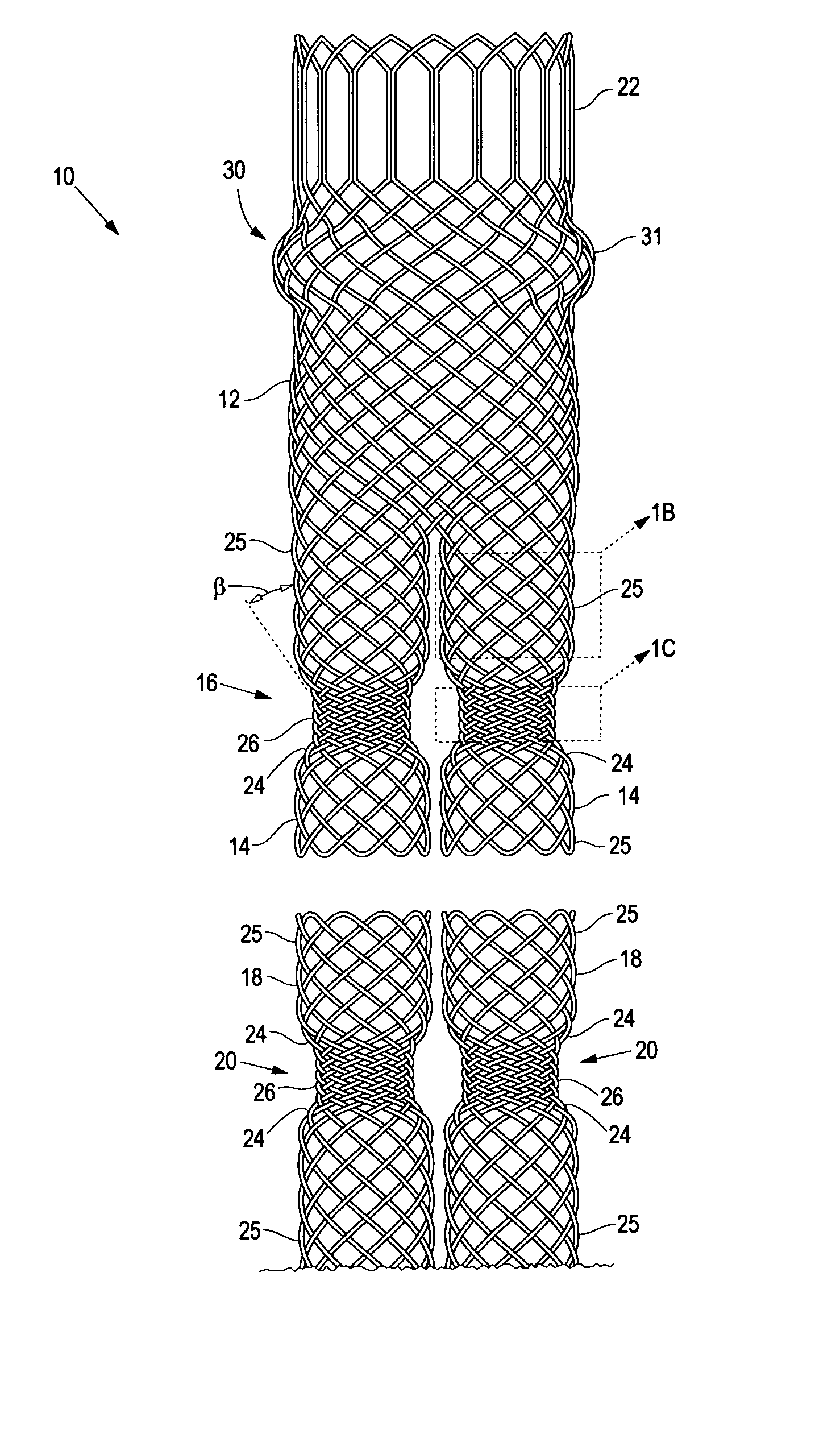
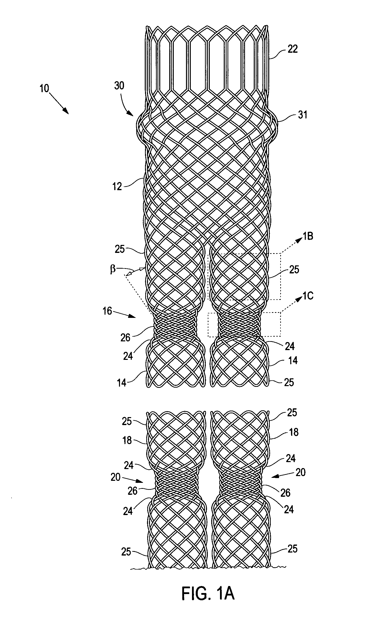
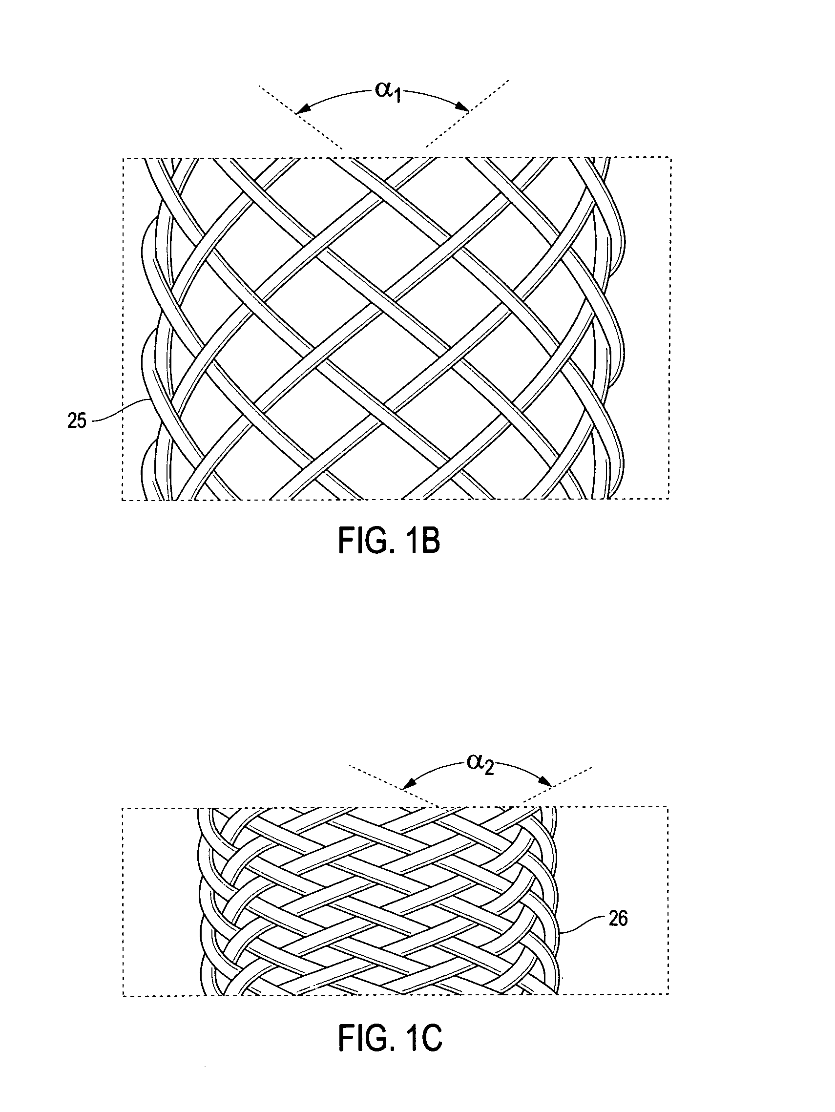
[0030]Referring now to FIGS. 1A–1C, there is shown a modular bifurcated stent 10 of the present invention. The stent comprises three modular sections: a body 12 having two leg stumps 14 having first hourglass-shaped interfaces 16, and a pair of legs 18, each having a second hourglass-shaped interface 20 adapted to interlock with one of the first interfaces. Body 12 further comprises a wound end section 22 having a hexagonal cell architecture. End section 22 may comprise any form of wound architecture, as described in U.S. patent application Ser. No. 09 / 442,165, filed Nov. 16, 1999, by Chouinard et al., assigned to the common assignee of this invention, and incorporated herein by ref...


PUM


Abstract

A braided modular stent comprising a first component and a second component, each component comprising an hourglass-shaped interface having a reduced diameter section positioned between two sloped sections. Each sloped section extends between the reduced diameter section and one of a plurality of nominal diameter sections. The reduced diameter section has a greater radial strength than the nominal diameter sections. One of the components may have a sealing region, such as a circumferential elevation, for providing an endoleak-resistant seal between the stent and a body lumen. One exemplary method for fabricating a circumferential elevation comprises affixing a plurality of filaments, such as sutures, between overlaps of braided filaments in one region and overlaps in another region.

Description

BACKGROUND OF THE INVENTION[0001]1. Technical Field[0002]This invention relates generally to endoluminal devices and, more specifically, to a stent having an integral sealing ring.[0003]2. Background of the Invention[0004]A stent is an elongated device used to support an intraluminal wall. Stents may also have a prosthetic graft layer of fabric or covering lining the inside or outside thereof, such a covered stent being commonly referred to in the art as an intraluminal prosthesis, an endoluminal or endovascular graft (EVG), or a stent-graft. A prosthesis may be used, for example, to treat a vascular aneurysm by removing the pressure on a weakened part of an artery so as to reduce the risk of rupture. Stents and prostheses are typically introduced into a lumen in a compressed state and expanded to an expanded state by self-expansion, balloon-expansion, or a combination thereof.[0005]Various stent architectures are known in the art, including filamentary and cut tube architectures. B...

Claims


Application Information

Patent Timeline
Patent Type & Authority Patents(United States)
IPC IPC(8): A61F2/06A61F2/00A61F2/90
CPCA61F2/90D04C3/48D04C1/06A61F2002/067A61F2250/0018A61F2250/0039D10B2509/06A61F2220/0075D10B2403/0331
Inventor SOUN, NAROUNUN, KIMBERLYTHISTLE, ROBERT C.LALIBERTE, RAYMOND J.
Owner LIFESHIELD SCI
Learn More