Rotating filter

a rotating filter and liquid filter technology, applied in the direction of filtration separation, moving filter element filter, water/sludge/sewage treatment, etc., can solve the problem that all these requirements cannot be fulfilled to the desired extent, and achieve the effect of convenient and reliable assembly

Inactive Publication Date: 2006-04-18
WESTFALIA SEPARATOR AG
View PDF43 Cites 21 Cited by
  • Summary
  • Abstract
  • Description
  • Claims
  • Application Information

AI Technical Summary

Benefits of technology

[0010]It is the task of the invention to develop a device of the initially described kind in such a manner that a perfect axial and radial positioning of the disks results, that the impermeability against passing of

Problems solved by technology

All these requirements could not be fulfilled to

Method used


Image

  • Rotating filter
  • Rotating filter
  • Rotating filter

Examples


Embodiment Construction

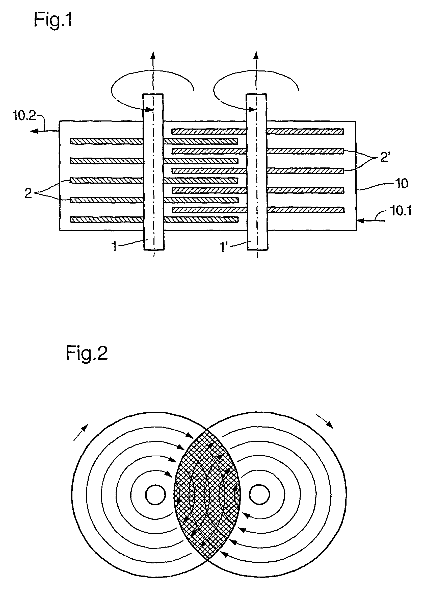
[0034]As can be seen in FIGS. 1 and 2, the device comprises two hollow shafts 1, 1′. Each hollow shaft carries a stack of disks 2, 2′. The two shafts 1, 1′ and the disk stacks are in a reservoir 10. The reservoir includes an inlet 10.1 and an outlet 10.2.

[0035]The two hollow shafts 1, 1′ are driven—see FIG. 2, seen in top view on the ends of the shafts in the counterclockwise direction. They can run also in the clockwise direction. The rotation in the same direction of rotation is preferred.

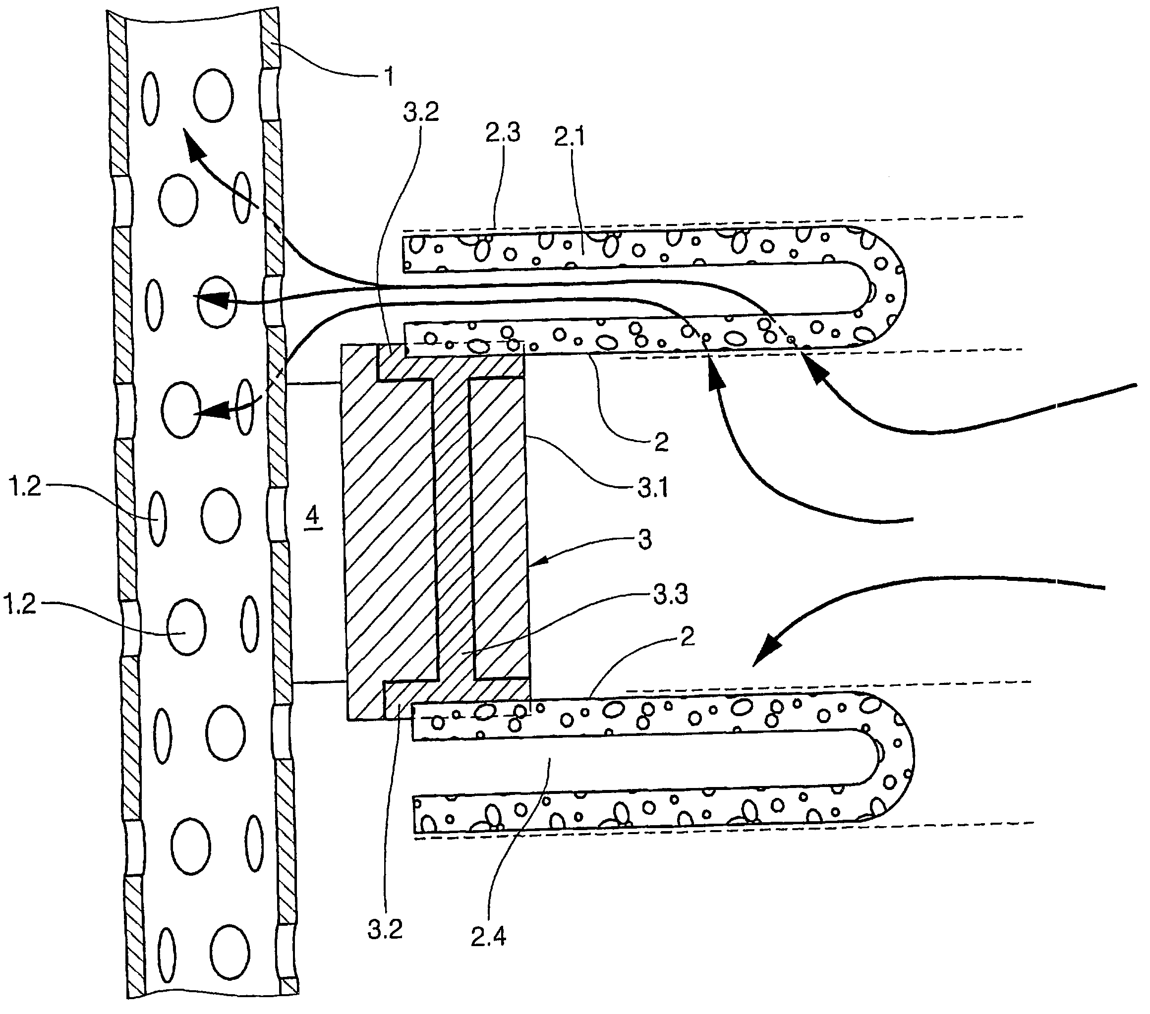
[0036]In the present case the disks 2 and 2′ serve the purpose of filtration. They are composed of a porous ceramic material and exhibit internal channels. The channels are in conducting connection with the insides of the hollow shafts 1, 1′.

[0037]The medium to be treated arrives in the inside of the reservoir 10 through the inlet 10.1. The filtrate / permeate enters then through the pores of the ceramic material the channels mentioned and arrives from there in the inside of the two hollow shafts 1...


PUM

PropertyMeasurementUnit
Lengthaaaaaaaaaa
Angleaaaaaaaaaa
Flow rateaaaaaaaaaa

Abstract

A device for filtering liquids comprising two shafts which are parallel to each other or at an acute angle wherein each shaft carries a stack of disks that extend perpendicularly to the shaft axis and are rotated thereby. The disks of one stack are engaged in the intermediate spaces of an adjacent disk stack and at least one of the shafts is driven. At least one of the shafts is hollow and is provided with bores and some of the disks have channels therein which are fluidly connected to the inside of their respect hollow shaft. A support ring is oversized in relation to the shaft so that a channel is formed between the inner surface of the support ring and the outer surface of the shaft and this channel extends over at least part of the length of the shaft.

Description

BACKGROUND OF THE INVENTION[0001]The invention relates to a device for filtering liquids. Such a device is described for example in DE 100 19 672 A1.[0002]Devices of this kind serve the cross-flow permeation of free-flowing media. They contain at least two shafts, onto which in each case many disk-shaped diaphragm bodies are arranged parallel to each other and in mutual distance. The shafts are hollow, and the diaphragm disks are made of ceramic material and are burred with radial channels. Between the radial channels and the inside of the hollow shaft is a conducting connection. The liquid to be filtered arrives from the outside through the porous material of the diaphragm body into the channels, and from there into the hollow shaft.[0003]The shafts mentioned run parallel to each other, so that also the diaphragm disks of two each other adjacent disk stacks are arranged parallel to each other. The shafts are arranged so close next to each other in such a manner that the disks of tw...

Claims


Application Information

Patent Timeline
IPC IPC(8): B01D33/23B01D33/21B01D63/08B01D63/16
CPCB01D33/21B01D63/084B01D63/16B01D33/37B01D33/52B01D33/68
Inventor BLASE, DIETEROLAPINSKI, HANSFEUERPEIL, HANS-PETER
Owner WESTFALIA SEPARATOR AG
Why Eureka
Try Eureka