Pre-cut fibrous insulation for custom fitting wall cavities of different widths

a technology of fibrous insulation and wall cavities, which is applied in the field of pre-cut fibrous insulation for custom-fitting wall cavities of different widths, can solve the problems of increasing material costs, raising significant risk or safety issues, and time-consuming methods of forming insulation batts or panels on the job site, so as to speed up the installation process, reduce safety concerns, and be quick and easy to fi

Inactive Publication Date: 2006-04-18
JOHNS MANVILLE CORP
View PDF9 Cites 16 Cited by
  • Summary
  • Abstract
  • Description
  • Claims
  • Application Information

AI Technical Summary

Benefits of technology

[0009]Do to the compressibility and resilience of the pre-cut fibrous insulation blankets of the present invention (generally pre-cut glass fiber insulation blankets), the pre-cut fibrous insulation blankets can be fitted into cavities having a width up to about one and one half inches less than the width of the pre-cut fibrous insulation blankets without removing any sections of the blankets, e.g. a pre-cut fibrous insulation blanket having a width between about fourteen and one half to about fifteen inches can be installed within a cavity having a width of about thirteen inches or greater. For cavities of lesser widths, greater than about one and one half inches less in width than the pre-cut fibrous insulation blankets, the pre-cut fibrous insulation blankets may have one or more sections removed from the blankets so that the remaining portions of the pre-cut fibrous insulation blankets will better fit into the cavities being insulated.
[0010]The pre-cut fibrous insulation blanket of the present invention has at least one (preferably, two or more) series of cuts extending between a first major surface to a second major surface of the pre-cut fibrous insulation blanket with successive cuts of each series of cuts being separated by a series of separable connectors located intermediate the major surfaces of the pre-cut fibrous insulation blanket. Each series of cuts and separable connectors extend for the length of the pre-cut fibrous insulation blanket with each series of separable connectors holding together adjacent sections of the pre-cut fibrous insulation blanket for handling and being separable by hand whereby the pre-cut fibrous insulation blanket can be handled as a unit for insulating a cavity having a predetermined width, such as but not limited to a standard cavity width, or easily separated by hand into two or more sections at each series of separable connectors for insulating a cavity of lesser width, such as a cavity having less than a standard width.
[0011]The first or second major surface of the pre-cut fibrous insulation blanket may have a facing bonded thereto which, preferably, has one or more perforated lines or overlapping tabs (tabs which are adhesively bonded together), and / or tear strings for permitting the facing to be separated at each series of cuts and separable connectors in the pre-cut fibrous insulation blanket to facilitate separating or tearing apart the faced pre-cut insulation blanket by hand, if required. Preferably, the perforations of the perforated line(s).in the facing are closed by the bonding agent bonding the facing to the pre-cut fibrous insulation blanket. The filling of the perforations in the facing with the bonding agent helps to reinforce or increase the integrity of the facing at the perforations to prevent an unwanted separation of the facing at the perforations and enables the facing to function as a vapor barrier in spite of the perforations. Thus, the pre-cut fibrous insulation blanket with the facing can still be quickly and easily modified to fit a cavity of a particular width without sacrificing the vapor barrier properties of the facing sheet.
[0013]With the faced or unfaced pre-cut fibrous insulation blanket of the present invention, the pre-cut fibrous insulation blanket can be quickly and easily sized to fit wall, floor, ceiling, roof and other building cavities formed by the framework of a building without the need to use cutting tools at the job site to cut the insulation. Thus, the use of the pre-cut fibrous insulation blanket of the present invention to insulate the wall, floor, ceiling and roof cavities of buildings, especially wall cavities, not only reduces safety concerns, but greatly speeds up the installation process. Since insulation installers are frequently paid by the piece, the present invention enables them to operate more profitably.

Problems solved by technology

This method of trimming the insulation batts at the job site by cutting the batts to fit between the more closely spaced support members is time consuming, raises a significant risk or safety issue, relies heavily on the worker's skill to accurately trim the batt or panel.
Of course this method of forming insulation batts or panels at the job site is also time consuming and relies heavily on the skill of the worker cutting the insulation strip to achieve a good result.
In addition, the extra insulation material used to insulate cavities having less than a standard cavity width would add significantly to material costs.
Thus it can be seen that there has been a need to provide fibrous insulation blankets or batts which can be used to either insulate cavities of a predetermined width, such as but not limited to standard width framework cavities, or be quickly and easily reduced in width to fit cavities of lesser widths, such as less than standard width cavities, without a need to cut the fibrous insulation blankets at the job site with knives or similar cutting tools which is both time consuming and can result in cuts or other injuries to the workers.

Method used


Image

  • Pre-cut fibrous insulation for custom fitting wall cavities of different widths
  • Pre-cut fibrous insulation for custom fitting wall cavities of different widths
  • Pre-cut fibrous insulation for custom fitting wall cavities of different widths

Examples


embodiment 20

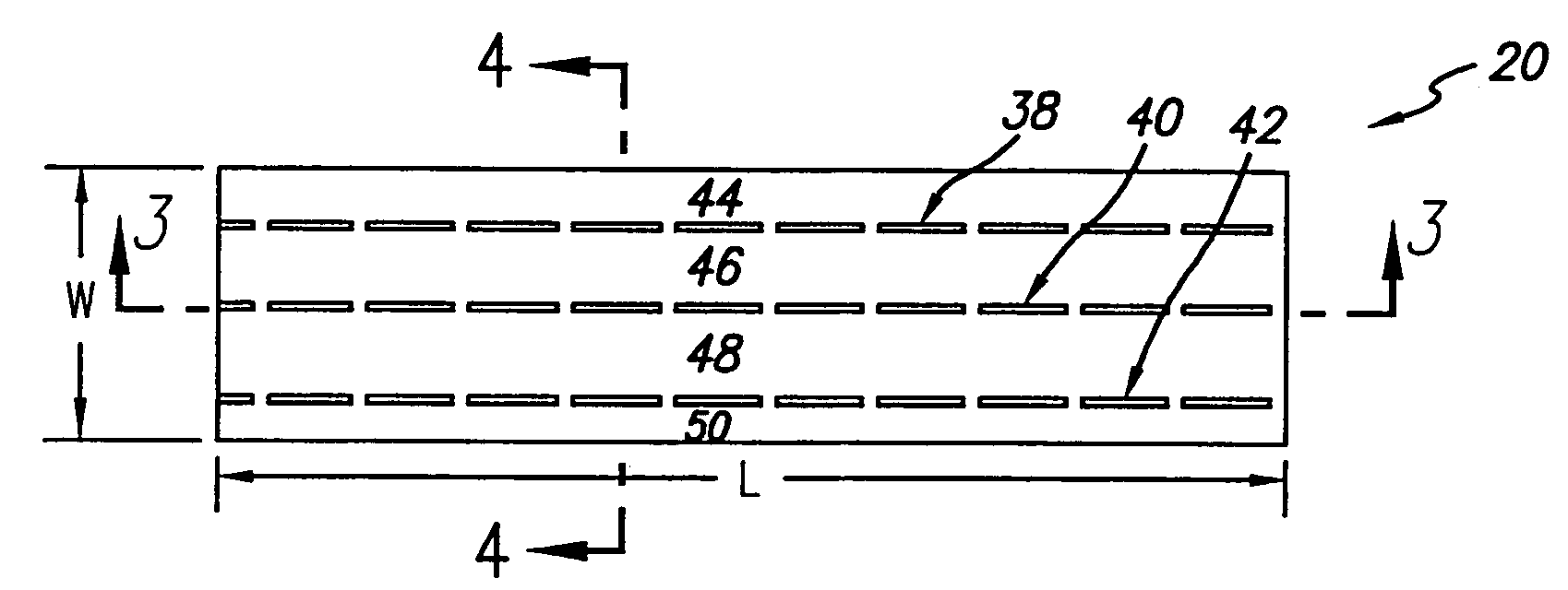
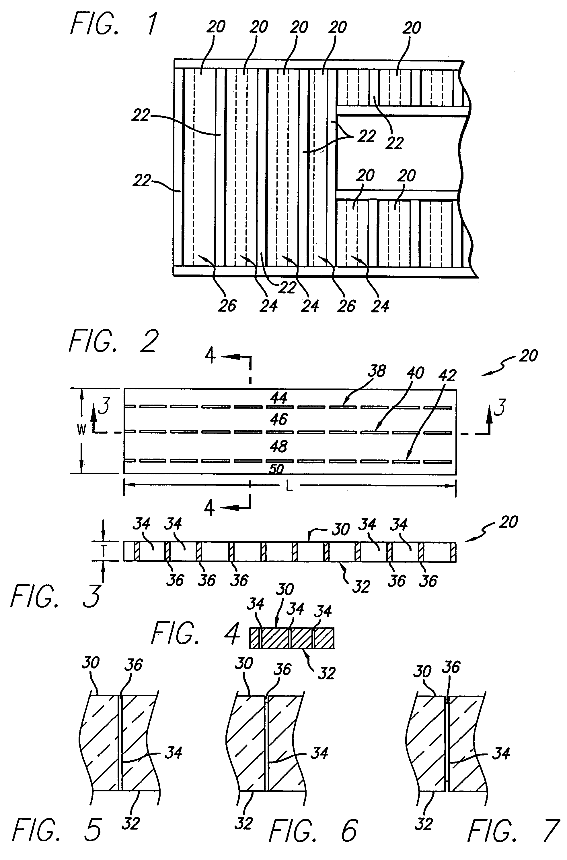
[0038]FIGS. 2 to 4 show an unfaced embodiment 20 of the pre-cut fibrous insulation blanket of the present invention. The pre-cut fibrous insulation blanket has a length “L”, a width “W” and a thickness “T”. A first major surface 30 and a second major surface 32 of the pre-cut fibrous insulation blanket 20 are each defined by the width “W” and length “L” of the insulation blanket. There are one or more series of cuts 34 and separable connectors 36, preferably two or three series of cuts and separable connectors (three series of cuts and separable connectors 38, 40 and 42 are shown) which extend for the length of the pre-cut fibrous insulation blanket 20. Each series of cuts 34 and separable connectors 36 divide the pre-cut fibrous insulation blanket 20 into blanket sections with the pre-cut fibrous insulation blanket being divided lengthwise into two or more blanket sections and, preferably, three or four blanket sections (four blanket sections 44, 46, 48 and 50 are shown) extending ...

embodiment 120

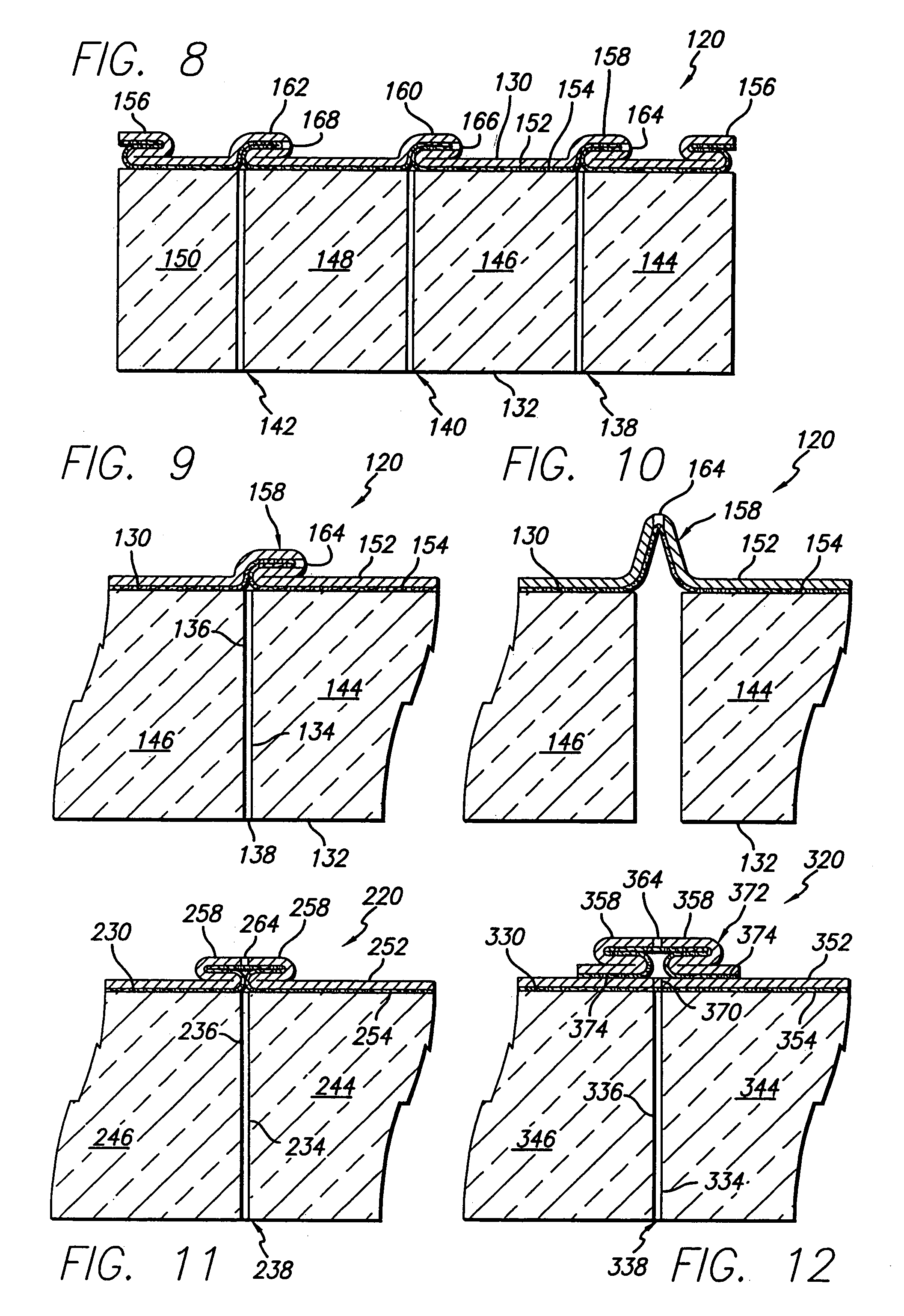
[0044]FIGS. 8 to 10 show a faced embodiment 120 of the pre-cut fibrous insulation blanket of the present invention. As shown, the faced pre-cut fibrous insulation blanket 120 of FIGS. 8 to 10 has a first major surface 130 and a second major surface 132. There are one or more series of cuts 134 and separable connectors 136, preferably two or three series of cuts separable connectors (three series of cuts and separable connectors 138, 140 and 142 are shown) in the faced pre-cut fibrous insulation blanket which extend for the length of the faced pre-cut fibrous insulation blanket 120. Each series of cuts 134 and separable connectors 136 divide the faced pre-cut fibrous insulation blanket 120 into blanket sections with the faced pre-cut insulation blanket being divided lengthwise into two or more blanket sections and, preferably, three or four blanket sections (four blanket sections 144, 146, 148 and 150 are shown) extending the length of the faced pre-cut fibrous insulation blanket.

[00...

embodiment 420

[0057]FIGS. 14 and 15 show a faced embodiment 420 of the pre-cut fibrous insulation blanket of the present invention. As shown, the faced pre-cut fibrous insulation blanket 420 of FIGS. 14 and 15 has a first major surface 430 and a second major surface 432. There are one or more series of cuts 434 and separable connectors 436, preferably two or three series of cuts separable connectors (three series of cuts and separable connectors 438, 440 and 442 are shown) in the faced pre-cut fibrous insulation blanket which extend for the length of the faced pre-cut fibrous insulation blanket 420. Each series of cuts 434 and separable connectors 436 divide the faced pre-cut fibrous insulation blanket 420 into blanket sections with the faced pre-cut insulation blanket being divided lengthwise into two or more blanket sections and, preferably, three or four blanket sections (four blanket sections 444, 446, 448 and 450 are shown) extending the length of the faced pre-cut fibrous insulation blanket...


PUM

PropertyMeasurementUnit
widthaaaaaaaaaa
lengthaaaaaaaaaa
thicknessaaaaaaaaaa

Abstract

An elongated fibrous insulation blanket is pre-cut for custom fitting the insulation blanket into wall, floor, ceiling and roof cavities of different widths formed by the framework of a building. The blanket has at least one, preferably two or three, series of cuts extending between major surfaces of the blanket with successive cuts of each series of cuts being separated by a series of separable connectors located intermediate the major surfaces of the blanket. Each series of separable connectors hold together adjacent sections of the blanket for handling, but are separable by hand so that the blanket can be handled as a unit for insulating a cavity having a predetermined width or easily separated by hand into two or more sections at one or more of the series of separable connectors for insulating a cavity having a lesser width. Either major surface of the blanket may have a facing bonded thereto with one or more perforated lines or overlapping tabs in the facing permitting the facing to be separated by hand at each series of cuts and separable connectors. Preferably, the perforations of any perforated line(s) in the facing are closed by the bonding agent bonding the facing to the blanket so that the facing functions as a vapor barrier in spite of the perforations.

Description

[0001]This application is a continuation of application Ser. No. 09 / 770,040 filed Jan. 24, 2001, now U.S. Pat. No. 6,670,011, which is a continuation-in-part of application Ser. No. 09 / 713,354, filed Nov. 10, 2000, now abandoned, which is a continuation-in-part of application Ser. No. 09 / 522,976, filed Mar. 10, 2000, now U.S. Pat. No. 8,165,305, which is a division of application Ser. No. 09 / 167,783, filed Oct. 7, 1998, now U.S. Pat. No. 6,083,594.BACKGROUND OF THE INVENTION[0002]The present invention relates to a fibrous insulation blanket pre-cut for custom fitting the fibrous insulation blanket into cavities of different widths formed by the framework of a building, such as both standard and non-standard width wall, floor, ceiling or roof cavities formed in part by successive frame members; and, in particular, to a pre-cut fibrous insulation blanket that can be handled as a unit when insulating a cavity of a certain predetermined width or easily separated or torn apart (by hand) ...

Claims


Application Information

Patent Timeline
Patent Type & Authority Patents(United States)
IPC IPC(8): B32B3/10B32B5/26B32B38/04E04B1/74E04B1/76
CPCB32B5/26E04B1/7654E04B1/7662E04B1/767B32B38/04Y10T428/24174B32B2038/047B32B2307/304B32B2395/00E04B2001/741E04B2001/7695Y10T428/24231Y10T428/187Y10T156/1064Y10T428/24256Y10T428/15Y10T428/24215Y10T428/24264Y10T428/183Y10T442/30
Inventor WEINSTEIN, LARRY J.ALLWEIN, ROBERT J.
Owner JOHNS MANVILLE CORP
Why Eureka
Try Eureka