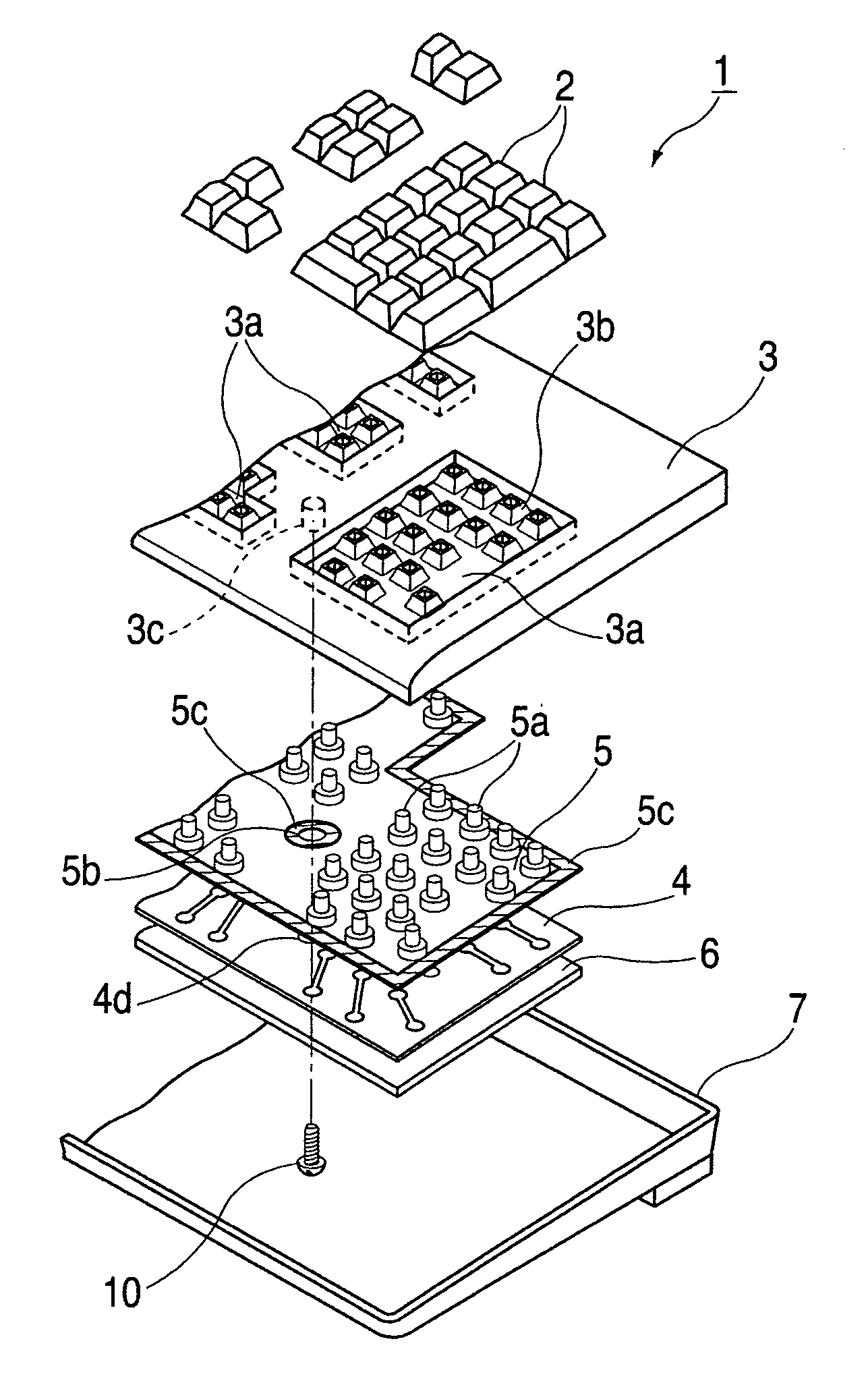
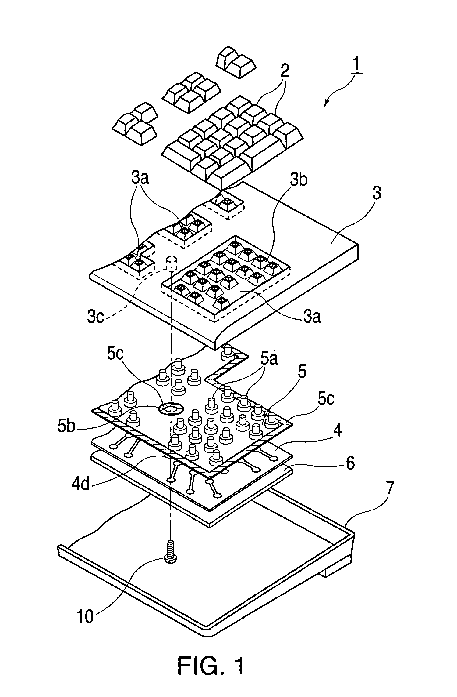
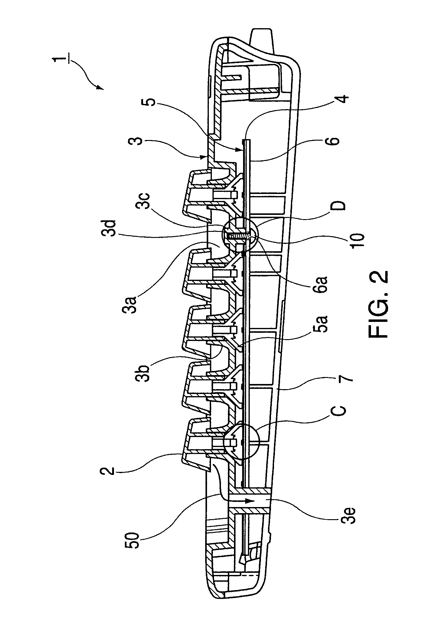
[0022]Referring to FIGS. 1–7, we provide detail descriptions of various embodiments of the keyboard spill-proofing mechanism disclosed in the present invention.
[0023]FIG. 1 shows an exploded view of a spill-proofing keyboard. As shown in FIG. 1, a keyboard 1 includes a plurality of key caps 2 and top case 3. Top case 3 fits together with key caps 2 so as to allow key caps 2 to slide freely. Top case 3 is substantially rectangularly shaped and made of synthetic resin. Moreover, top case 3 has concave areas 3a in which each key cap 2 is positioned. Top case 3 also has multiple hollow bosses 3b that are integrally formed inside concave areas 3a so as to provide a specified space or gap in the left-right and up-down directions. Key caps 2 fit into hollow bosses 3b so as to allow key caps 2 to move freely in the vertical direction. Multiple connecting bosses 3c are formed in top case 3 and project downward therefrom. Connection bosses 3c serve to connect top case 3 to back plate 6 by penetrating through waterproof base sheet 5 and membrane sheet 4. Connecting bosses 3c are formed to be approximately cylindrically or elliptically shaped. Waterproof base sheet 5 is positioned below top case 3. Waterproof base sheet 5 may be made from an adhesive material such as PET film or the like and is substantially rectangular in shape. Waterproof base sheet 5 also contains a plurality of rubber springs 5a that allow vertical movement of key caps 2 to be transmitted to membrane sheet 4.
[0024]Membrane sheet 4 contains through-holes 4d and is positioned below waterproof base sheet 5. Back plate 6 is positioned below membrane sheet 4. Back plate 6 may be made from a thin metal or the like and has a rectangular-shape similar to that of membrane sheet 4. Bottom case 7 is positioned below back plate 6. Attachment screws 10 are inserted through back plate 6, waterproof base sheet 5 and membrane sheet 4 and into connecting boss 3c of top case 3 so as to securely maintain the relative positions of back plate 6, membrane sheet 4 and waterproof base sheet 5 to top case 3.
[0025]FIG. 2 shows a cross sectional view of a spill-proofing keyboard. As shown in FIG. 2, keyboard 1 further includes insertion holes 3d which are formed on the ends of connecting bosses 3c so that attachment screws 10 can be inserted therein. Keyboard 1 also has drain hole 3e formed in the lower part of top case 3. Drain hole 3e is designed so that the majority of any liquid spilled on keyboard 1 and which penetrates key caps 2 would flow through drain hole 3e and out through bottom case 7 of keyboard 1, as shown by arrow 50. Bottom case 7 may be made of a synthetic resin or the like and is formed to have a box shape or rectangular shape so as to provide a housing for waterproof base sheet 5, and membrane sheet 4. At specified positions bottom case 7 is attached to top case 3 by attachment screws (not shown). Multiple penetrating holes 6a are formed in back plate 6 that are penetrated by attachment screws 10 which screw into connecting bosses 3c in top case 3. Penetrating holes 6a are formed in positions that correspond to those of connecting bosses 3c in top case 3. Structures shown in FIG. 2 as C and D include top case 3, membrane sheet 4, base sheet 5, and back plate 6 will be described in further detail in FIG. 6.
[0026]FIG. 3 shows the waterproof base sheet that is a constituent part of the spill-proofing keyboard. As shown in FIG. 3, a plurality of cone-shaped rubber springs 5a are connected to waterproof base sheet 5 and project upwardly leaving a specified gap in the left-right and up-down directions. Rubber springs 5a may be connected with adhesive or the like to cause rubber springs to adhere to the surface of waterproof base sheet 5. In addition, a plurality of circular or elliptical openings 5b are formed at specified positions in waterproof base sheet 5. Connecting bosses 3c that are formed in top case 3 penetrates openings 5b. Blocking portions 5c, which are shown as heavy or bold black lines, are of specified width and formed in the silicon-based adhesive layer. Block portions are formed around the entire perimeter of openings 5b. Main plane 5d is the main portion of waterproof base sheet 5. As shown in FIG. 3, blocking portions 5c are also formed around the entire outer perimeter of waterproof base sheet 5.
[0027]FIG. 4 is a cross sectional view along the line A—A in FIG. 3. As shown in FIG. 4, block portions 5c surround the entire perimeter of openings 5b. Blocking portions 5c project upwardly at a fixed height H from waterproof base sheet 5 main plane 5d. The fixed height H may be approximately 0.2 mm.
[0028]FIG. 5 is a cross sectional view along the line B—B in FIG. 3. As shown in FIG. 5, blocking portions 5c are also formed around the entire outer perimeter of waterproof base sheet 5 and are positioned on top of main plane 5d. Block portions 5c project upwardly at a fixed height H from waterproof base sheet 5 main plane 5d. The fixed height H may be approximately 0.2 mm.
[0029]FIG. 6 is an expanded cross sectional view of the C portion of FIG. 2. As shown in FIG. 6, membrane sheet 4 includes several layers each made of a laminated material or the like. The embodiment of the present invention depicted in FIG. 6 includes upper membrane sheet 4a, spacer sheet 4b and lower membrane sheet 4c. Upper membrane sheet 4a and lower membrane sheet 4c each contain an electrical circuit. Spacer sheet 4b is positioned between upper membrane sheet 4a and lower membrane sheet 4c.
[0030]FIG. 7 is an expanded cross sectional view of the D portion of FIG. 2. As shown is FIG. 7, through-holes 4d are formed in each laminated layer of membrane sheet 4. Through-holes 4d of membrane sheet 4 and openings 5b of waterproof base sheet are penetrated by top case 3 connecting bosses 3c. Also shown in FIG. 6 are penetrating holes 6a that are formed in back plate 6 which allow attachment screws 10 to penetrate back plate 6 and, through corresponding openings 5b of waterproof base sheet 5 and through-holes 4d of membrane sheet 4, to engage connecting bosses 3c. The columnar portions of key caps 2 are engaged with top case 3 hollow bosses 3b so as to slide freely and to contact the upper surface of rubber springs 5a that is adhered to waterproof base sheet 5. Waterproof base sheet 5 and membrane sheet 4 are mounted over back plate 6. Liquid droplet 51 is shown on main plane 5d.
[0031]FIGS. 2 and 6 also show that key caps 2 move in the vertical direction and engage top case 3 connecting bosses 3c so as to slide freely. The vertical movement of key caps 2 causes rubber spring 5a of waterproof base sheet 5 to also move vertically or in the up and down direction as shown by the arrows in FIG. 6. The movement of key caps 2 causes the on/off state of key caps 2 to be transmitted to the electrical circuit in upper membrane sheet 4a.
[0032]The keyboard waterproof mechanism of the present invention can therefore significantly reduce or eliminate any damage that may result from the accidental spilling of liquids onto the keyboard. Accordingly, when a liquid is spilled on the keyboard of the present invention, the majority of the liquid that leaks between key caps 2 will flow into drain holes 3e and drain out from the keyboard, as shown by arrows 50 in FIG. 2. As shown in FIG. 7, to avoid causing irreparable damage to the electronic circuits and components housed therein, blocking portion 5c of waterproof base sheet 5, which is positioned below top case 3, is designed so that small quantities of excess liquid 51 that are not drained of into drain holes 3e do not further penetrate downward into the keyboard. Blocking portion 5c are formed around the edge of openings 5b in waterproof base sheet 5 and project upward from main plane 5d. The upward projection of blocking portion 5c prevents any liquid on the surface of main plane 5d from entering or flowing into openings 5b and onto membrane sheet 4 positioned below waterproof base sheet 5.
[0033]In accordance with one embodiment of the present invention any small quantity of excess liquid that is spilled onto top case 3 and flows onto waterproof base sheet 5 will be prevented from flowing onto and damaging membrane sheet 4 by causing electrical short or other electrical problems. More specifically, waterproof base sheet 5 is designed such that upward projects are formed in waterproof base sheet 5 around openings 5b that ensure that the flow of liquid is prevented from entering such openings and flowing onto membrane sheet 4 below.
[0034]Further, in accordance with one embodiment of the present invention top case 3 and back plate 6 are connected by connecting bosses 3c which are disposed in top case 3 and penetrate openings in waterproof base sheet 5, and membrane sheet 4.
[0035]Further, in accordance with at least one embodiment of the present invention blocking portions 5c are formed in waterproof base sheet 5 and are of a specified height.
[0036]The block portions described above can be easily designed with simple structures so as to reduce manufacturing costs.
[0037]In the foregoing description, the apparatus of the present invention have been described with reference to specific examples. It is to be understood and expected that variations in the principles of the apparatus herein disclosed may be made by one skilled in the art and it is intended that such modifications, changes, and substitutions are to be included within the scope of the present invention as set forth in the appended claims. The specification and drawings are accordingly to be regarded in an illustrative rather than restrictive sense.