Thermal printer and control method of controlling cooling fan

Inactive Publication Date: 2006-04-18
FUJIFILM CORP +1
View PDF6 Cites 3 Cited by
  • Summary
  • Abstract
  • Description
  • Claims
  • Application Information

AI Technical Summary

Benefits of technology

[0014]According to the present invention, after estimating the head temperature in each recording position based on the printing rate determined from the image data, the air amount of the cooling fan is controlled on the basis of the estimated result, so that it is possible to control the air amount in response to the fluctuation of the head temperature. Thus, the head temperature can be stabilized near the target temperature. As a result, density difference between prints and density unevenness in the same print can be prevented.

Problems solved by technology

However, if printing is continuously performed, it is caused to accumulate heat in the thermal head, so that it becomes impossible to print the image of which density is appropriate.
In such printing, since the air amount of the cooling fan is large, the head temperature gradually becomes low during changing a corrugated form.
Therefore, density unevenness is created in the same print, and to make matters worse, density difference is generated between prints.
However, the head temperature is not enough to be controlled by the above-mentioned methods.
However, with respect to the fluctuation of the head temperature measured by the head temperature sensor, delay of Δt minutes occurs to the fluctuation of the actual head temperature.
This delay time is caused by a delay in both a heat transmitting system and a measuring system.
The delay in the heat transmitting system is attributable to an attachment position of the head temperature sensor, material of the thermal head and a heat sink, and a shape of an air flowing path for leading a cooling air sent from the cooling fan, while the delay in the measuring system is attributable to timing of temperature data acquisition in the head temperature sensor.
For example, if the black and white solid areas are printed alternately in the same printing paper, although the actual head temperature is lowered when printing the white solid area, it takes considerable time to reflect in the control of the air amount of the cooling fan after measuring such temperature change by the head temperature sensor.
When the air amount increases after detecting the temperature change by the head temperature sensor, the white solid area has already started to be printed, so that there is a problem that the actual head temperature is rapidly lowered.
Accordingly, since the control of the air amount of the cooling fan is delayed according to the kind of image to be printed, the fluctuation of the head temperature is not enough to be controlled, so that the density difference between prints and the density unevenness in the same print are created.

Method used


Image

  • Thermal printer and control method of controlling cooling fan
  • Thermal printer and control method of controlling cooling fan
  • Thermal printer and control method of controlling cooling fan

Examples


Embodiment Construction

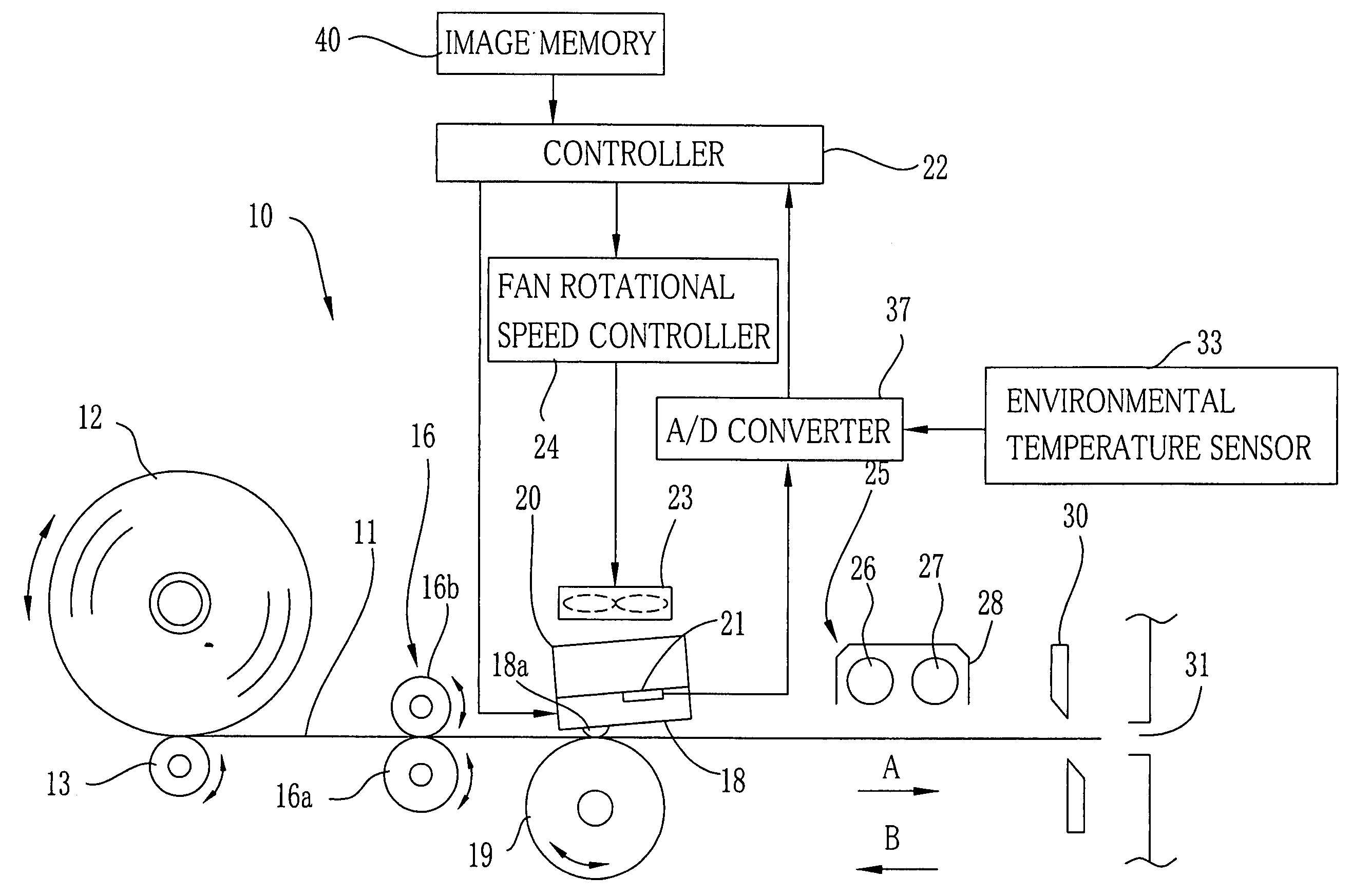
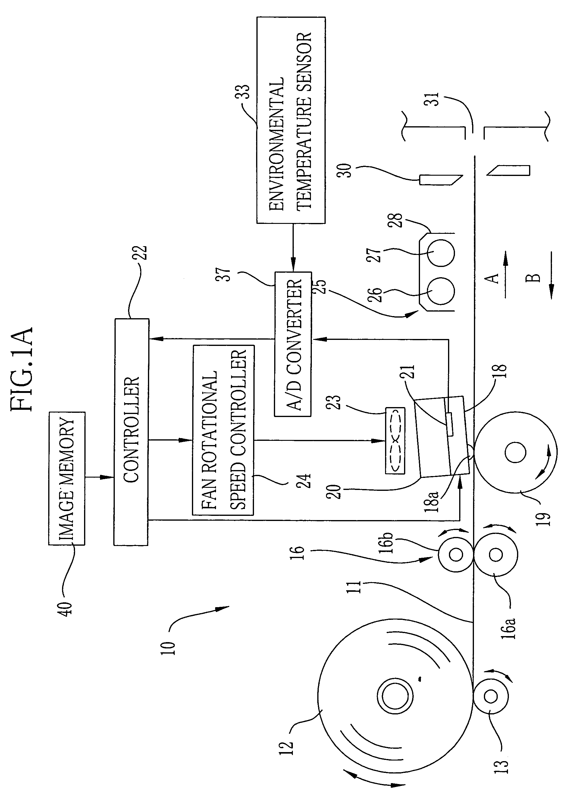
[0025]In FIG. 1, a continuous color thermal recording paper 11 (hereinafter referred to as a recording paper) is used in a color thermal printer 10 as a recording media. The recording paper 11 is wound into a roll shape and loaded into the color thermal printer 10 as a recording paper roll 12.

[0026]A feeder roller 13 for supply is in contact with an outer periphery of the recording paper roll 12. The feeder roller 13 is driven by a feeding motor (not shown). When the feeder roller 13 rotates in a clockwise direction, the recording paper roll 12 is rotated in a counter clockwise direction to feed the recording paper 11 from the recording paper roll 12. Whereas, when the feeder roller 13 is rotated in the counter clockwise direction, the recording paper roll 12 is rotated in the clockwise direction to withdraw the recording paper 11 thereto.

[0027]As well-known, the recording paper 11 includes a cyan thermosensitive coloring layer, a magenta thermosensitive coloring layer, and a yellow...


PUM


Abstract

A color thermal printer is provided with a cooling fan for cooling a thermal head and a fan rotational speed controller for controlling the rotation speed of the cooling fan, a head temperature sensor for measuring a temperature of the thermal head and an environmental temperature sensor for measuring an environmental temperature around the thermal head. A controller predicts the head temperature in each recording position based on the printing rate (printing density) calculated from the image data, a measured temperature of the thermal head and a measured environmental temperature, and also predicts a delay time of a heat transmitting system and a measuring system based on a fluctuation of the printing rate. The controller controls an air amount of the cooling fan in each recording position based on the predicted temperature and the delay time.

Description

BACKGROUND OF THE INVENTION[0001]1. Field of the Invention[0002]The present invention relates to a thermal printer having a cooling fan for cooling a thermal head and a control method of controlling the cooling fan.[0003]2. Description of the Prior Arts[0004]A thermal printer is provided with a thermal head in which plural heating elements are arranged in rows in a main scanning direction. An image is printed on a recording paper by heating the heating elements that are contacted with a surface of the recording paper while feeding the recording paper in a sub-scanning direction. In order to obtain a high quality image, the temperature of the thermal head (hereinafter referred to as the head temperature) needs to be kept appropriately. However, if printing is continuously performed, it is caused to accumulate heat in the thermal head, so that it becomes impossible to print the image of which density is appropriate. In order to prevent the heat accumulation in the thermal head, a heat...

Claims


Application Information

Patent Timeline
IPC IPC(8): B41J29/377B41J2/32B41J2/375
CPCB41J29/377B41J2/375
Inventor TSUBOTA, KEIJI
Owner FUJIFILM CORP
Why Eureka
Try Eureka