Device for the thermal treatment of yarns

a thermal treatment and yarn technology, applied in the direction of helical storage of textiles, cleaning using liquids, other washing machines, etc., can solve the problems of increasing the volume of threads, reducing the thermal treatment effect of yarns, so as to achieve low friction and not damage, the effect of low friction

Active Publication Date: 2016-02-11
SAURER TECH GMBH & CO KG
View PDF5 Cites 3 Cited by
  • Summary
  • Abstract
  • Description
  • Claims
  • Application Information

AI Technical Summary

Benefits of technology

[0031]It is particularly advantageous that the yarn-contacting side of the flexible material has low friction properties.
[0032]This advantageous configuration ensures that the threads lying on the transport means have an extremely gentle contact with the separating element and the fiber materials are not damaged by excessive friction. Furthermore, low friction surfaces generally have good resistance to abrasion.
[0033]In a further advantageous embodiment, the separating elements for thermal shielding are designed as a movable flap to minimise the exchange of media.
[0034]It is also possible within the scope of the invention that movable flaps or vanes can be designed as the separating elements which are mounted to be free and easily pivotable in the upper holder. Here too the weight of the materials used can influence the degree of surface load exerted on the threads lying on the transport means.

Problems solved by technology

In addition, the thermal treatment causes a shrink billowing of the thread which increases the volume of the thread.
In addition, in the region of the inlet opening narrow plates are also arranged which also make it more difficult for cold external air to enter.
The disadvantage of devices which clamp the thread between one or two rollers and the conveyor belt has proved to be that at the points where the placed threads cross over one another, pressure points are created over the length of a yarn diameter which are also fixed.
Said pressure points affect the uniformity of the yarn as in this area the compression is greater, which for example during dyeing and during later surface finishing results in an uneven product.
The conveyor belt with the threads lying thereon runs through the gore of the squeezing roller pairs or the rollers on the conveyor belt, and this has a negative effect particularly at the outlet opening, through which the recently heated threads run through the output roller(s) into the cooler atmosphere.
Furthermore, it can cause the flattening of the threads.
Furthermore, with slit screens and differently designed narrow outlets there is a risk that the threads can accumulate at the upper edge.
In particular, with a high density of threads and the associated high occupancy density there are displacements, accumulations and reorientations of the upper thread layers.
This can lead to catching during the subsequent removal of the threads from the conveyor belt.
Furthermore, the fiber materials can be damaged by friction on the sealing parts.
In addition, yarn climate barriers, ventilation barriers and the like are not only structurally expensive and increase the costs of a device for thermal treatment, but also the use / operation of such devices is expensive.

Method used


Image

  • Device for the thermal treatment of yarns
  • Device for the thermal treatment of yarns
  • Device for the thermal treatment of yarns

Examples


Embodiment Construction

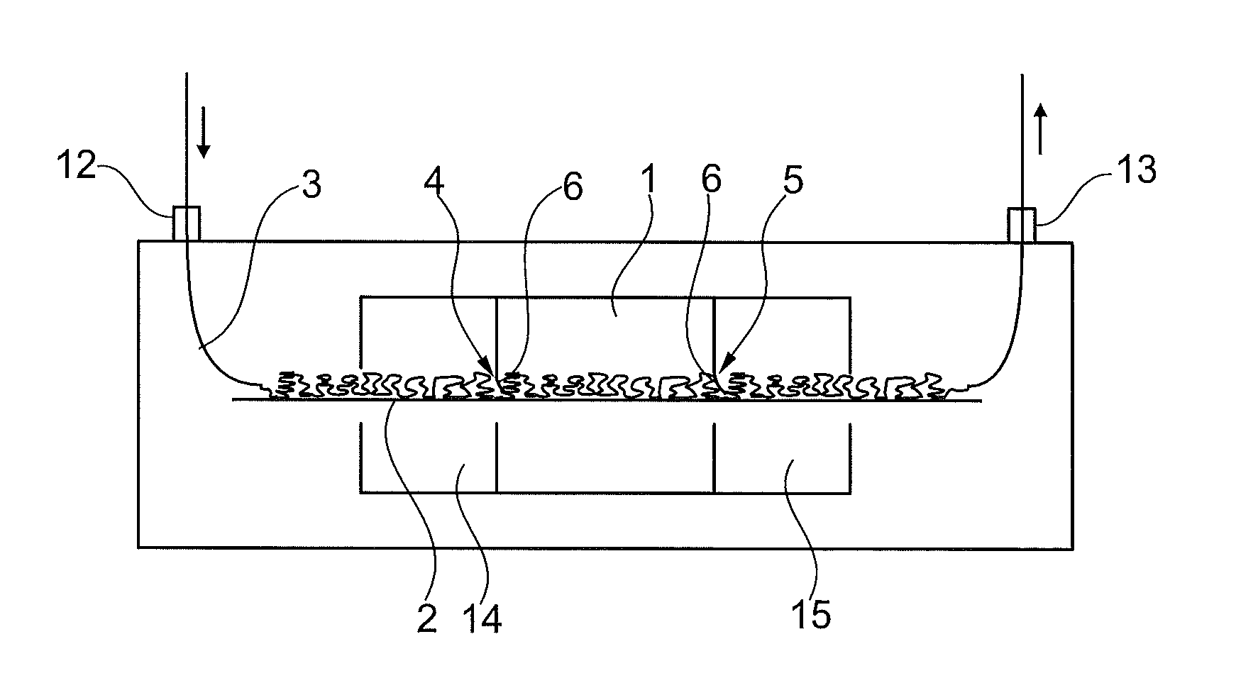
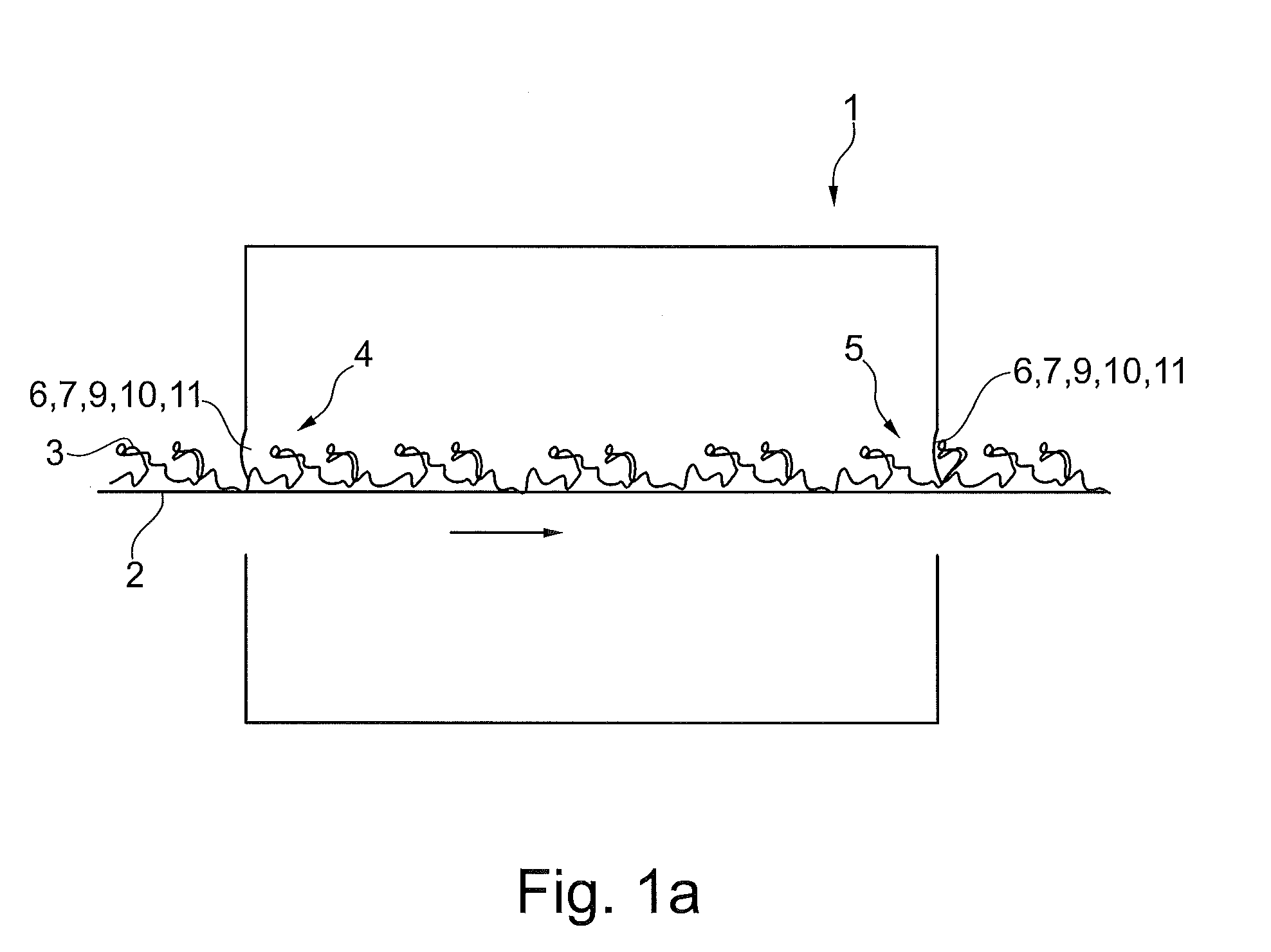
[0053]FIG. 1a shows schematically and in a much simplified form a device 1 for the thermal treatment of yarns 3.

[0054]Once the threads 3 have passed through a (not shown) shaping device and have been bent and / or crushed (crimped) three-dimensionally in a geometrically irregular manner, the thread mass lies on the transport means 2.

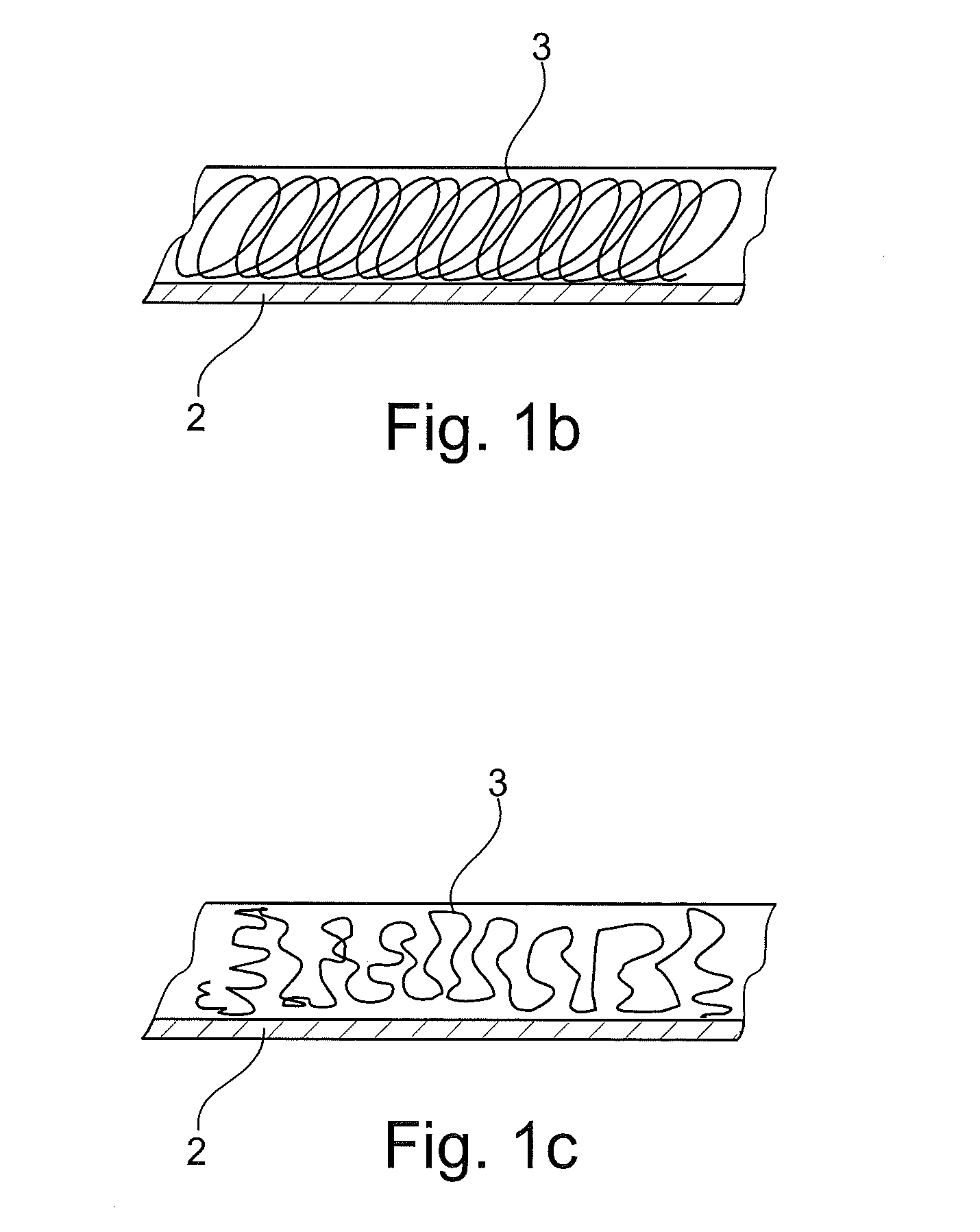
[0055]Of course, it is also possible within the scope of this application that the threads 3 are deposited linearly or in any other form on the transport means 2. FIG. 1b shows the depositing of yarn for so-called straight set threads, i.e. threads that are referred to as uncrimped threads disregarding the bending radii. FIG. 1c shows the deposit of frieze yarns which have a three-dimensional shape.

[0056]Lying on the transport means 2 the threads 3 first of all run through the inlet opening 4 and then the outlet opening 5 of the device 1 for thermal treatment which is operated by steam.

[0057]The heating is performed there up to the so-called heat-setting t...


PUM

PropertyMeasurementUnit
bending rigidityaaaaaaaaaa
flexibleaaaaaaaaaa
friction propertiesaaaaaaaaaa

Abstract

A device for the thermal treatment of yarns comprising at least one inlet opening and at least one outlet opening for at least one transport means, which transports the yarn through the device, and comprising separating elements at the inlet opening and the outlet opening for thermal shielding, in order to minimise the exchange of media to the environment. The separating elements are configured to have a low bending rigidity and are arranged such that a surface load is applied onto the yarn lying on the transport means, for example a conveyor belt, which is not greater than 0.005 kg*cm−2.

Description

CROSS-REFERENCE TO RELATED APPLICATIONS[0001]This application claims priority from German National Patent Application No. 10 2014 011 696.4, filed Aug. 7, 2014, entitled “Vorrichtung zur thermischen Behandlung von Garnen”, the entire contents of which are incorporated herein by reference.FIELD OF THE INVENTION[0002]The invention relates to a device for the thermal treatment of yarns comprising at least one inlet opening and at least one outlet opening for at least one transport means, which transports the yarn through the device, and comprising separating elements at the inlet opening and the outlet opening for thermal shielding, in order to minimise the exchange of media to the environment.BACKGROUND OF THE INVENTION[0003]To ensure that textiles fulfill their purpose and have the desired properties in terms of feel, appearance and behaviour when in use, they are processed specifically. In addition to the extraction of fibers, the production of yarns and threads and formation of sur...

Claims


Application Information

Patent Timeline
Patent Type & Authority Applications(United States)
IPC IPC(8): D02J13/00D06C7/02
CPCD06C7/02D02J13/00D06B17/005D06B23/16D06B23/18D02J13/001D06B23/00D06C15/06
Inventor BECKERS, JOACHIMBRENK, SIEGFRIEDDEITLAFF, MICHAELSINGER, SERGEIZISCHEWSKI, JORG
Owner SAURER TECH GMBH & CO KG
Why Eureka
Try Eureka