

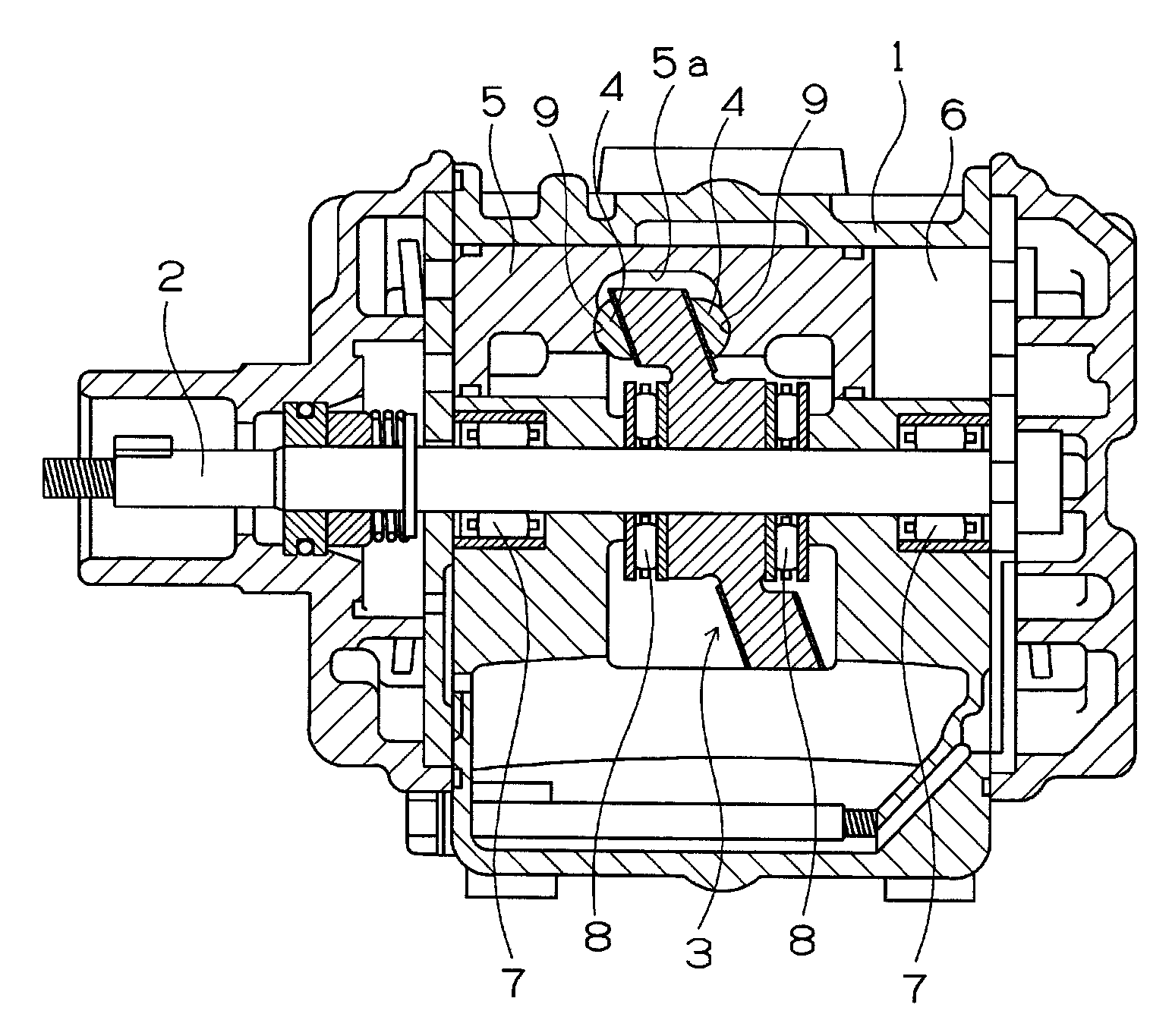
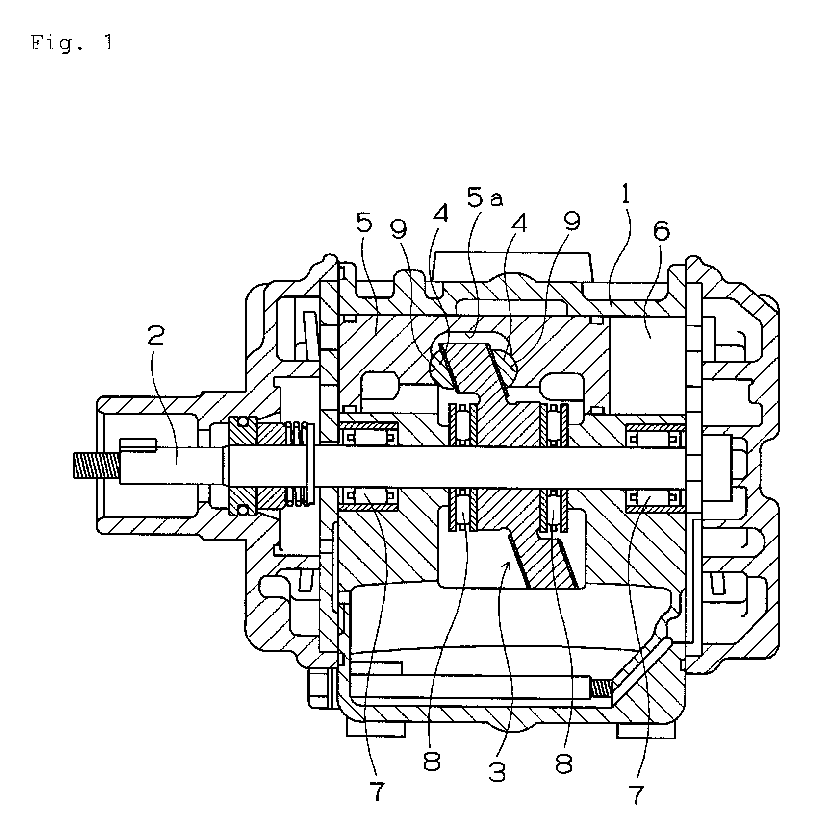
Swash plate for swash plate compressor and swash plate compressor
a technology of swash plate compressor and swash plate, which is applied in the direction of machines/engines, mechanical equipment, positive displacement liquid engines, etc., can solve the problems of sliding contact portions liable to seize, sliding portion of the swash plate is liable to seize to a higher extent than the sliding portion of the conventional swash plate, and achieves high adhesion of resin films, low friction properties, and high adhesion strength
- Summary
- Abstract
- Description
- Claims
- Application Information
AI Technical Summary
Benefits of technology
Problems solved by technology
Method used
Image

Examples
examples 1 through 8
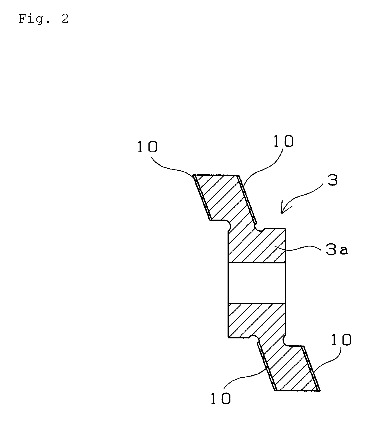
[0069]After a steel plate of each example made of SAPH440C was molded into the shape of a disk by pressing processing, rough processing was performed to set the thickness of each disk to thickness 6.5 mm, diameter 90 mm by using a lathe. Thereafter both surfaces of the disk was ground by using the double head grinding machine (grinding stone: #80) to set its flatness to not more than 5 μm, parallelism to not more than 5 μm, and thickness to 6.36 mm. Thereafter both ground surfaces of the base material of the disk were shot blasted (Rz: target was 5.0 μm) to enhance the surface roughness of both ground surfaces thereof. Thereafter each resin paint having the mixing ratio shown in table 1 was applied to both shot blasted surfaces of the base material of each disk by using a spray-coating method to such an extent that the resin paint was deposited in a thickness of 30 μm after the resin paint was calcined. After the resin paint was calcined at 240° C., both surfaces of the base materia...
examples 9 through 12
[0074]The base material of each of the examples was processed by using the same method as that of the example 1. Each resin paint having the same mixing ratio as that of the example 3 shown in table 1 was applied to both surfaces of the base material to such an extent that the resin paint was deposited in the thickness of 30 μm by using the spray-coating method after the resin paint was calcined. After the resin paint was calcined, both surfaces of the base material of each disk were ground by using a surface grinder to perform final finish processing (flatness was set to not more than 15 μm, parallelism was set to not more than 15 μm, thickness was set to 6.40 mm). In this manner, specimens of the examples were obtained. Thereafter four kinds of grinding stones (#2000, #600, #230, #120: for resin) were used to differentiate the surface roughnesses of the specimens from one another.
PUM
| Property | Measurement | Unit |
|---|---|---|
| flatness | aaaaa | aaaaa |
| depth | aaaaa | aaaaa |
| pressure | aaaaa | aaaaa |
Abstract
Description
Claims
Application Information