Storage medium and method for actuator movement control

a technology of actuator movement and storage medium, which is applied in the direction of magnetic recording, data recording, instruments, etc., can solve the problems of unintended large changes in speed, degrade the stability of speed control, and problems such as problems such as the detection of sensitivity of speed change determination, and achieve stable control operation and detection sensitivity. high

Active Publication Date: 2006-04-18
KK TOSHIBA
View PDF8 Cites 8 Cited by
  • Summary
  • Abstract
  • Description
  • Claims
  • Application Information

AI Technical Summary

Benefits of technology

[0028]It is a more specific object of the present invention to provide a storage device having high shock-resistance and vibration-resistance and capable of fast and stable loading / unloading operations, and a method of controlling movement of an actuator.
[0046]According to the present invention, in operations of loading or unloading the recording and reproducing head, the position of the recording and reproducing head is detected, and it is determined whether the position of the recording and reproducing head reaches a first predetermined position, and based on the result of the position determination, the bandwidth of the feedback control is switched to a wide bandwidth, or a predetermined feed-forward control variable is added to the feed-back control variable. As a result, it is possible to quickly and stably control the speed of the actuator.

Problems solved by technology

Similarly, in the loading operation, if the downward speed of the magnetic head is too high, the same problem may occur.
However, if the threshold value of the moving speed is set close to the target value so as to shorten the detection time Δt, detection errors may occur, and this may cause unintended large changes of the speed.
If the gain in the feedback control is set higher, oscillation may be induced easily, and this may degrade the stability of speed control.
For example, when the device is being carried or used in a vibratory environment, such as in a train, operational stability of the device cannot be secured.

Method used


Image

  • Storage medium and method for actuator movement control
  • Storage medium and method for actuator movement control
  • Storage medium and method for actuator movement control

Examples


first embodiment

[0096

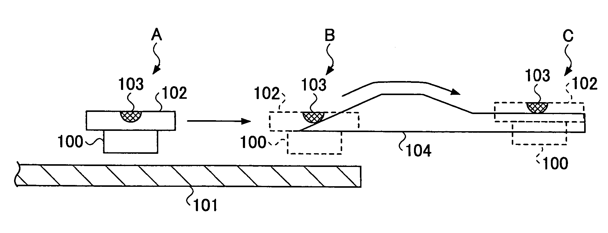
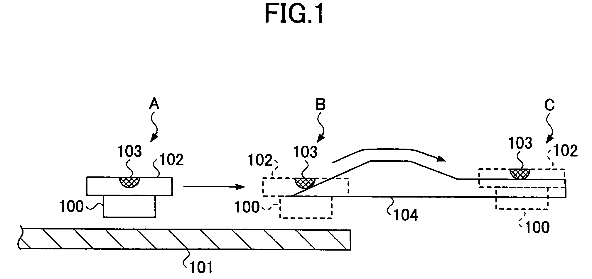
[0097]FIG. 3 is a plan view of a magnetic disk device 10 related to a first embodiment according to the present invention.

[0098]As shown in FIG. 3, the magnetic disk device 10 includes a magnetic disk 11, a magnetic head 12 for recording or reproducing information in the magnetic disk 11, and a disk enclosure 13 for accommodating the magnetic disk 11 and the magnetic head 12.

[0099]Furthermore, the magnetic disk device 10 includes an actuator 14 supporting and moving the magnetic head 12, a suspension 15 attached to the end of the actuator 14, a voice coil motor (VCM) 16 joined to the base portions 14a and 14b of the actuator 14, a pair of permanent magnets 18 arranged above and below the voice coil motor 16, a ramp 20 arranged close to the outer side of the magnetic disk 11 for unloading the magnetic head 12, a lift tab 21 attached to the end of the suspension 15 to raise the magnetic head 12 perpendicularly when the lift tab 21 moves on the ramp 20, an outer stopper 22 and an ...

second embodiment

[0224

[0225]A second embodiment of the actuator movement control method of the present invention is described below. The magnetic disk device of the present embodiment is the same as that of the first embodiment, and the same reference numbers are used for the same elements.

[0226]Specifically, the present embodiment relates to a method of controlling movement of the actuator 14 in the operation of loading and unloading the magnetic head 12.

[0227]The actuator movement control method of the present embodiment is basically the same as that of the first embodiment, except that the definitions of the position thresholds are different.

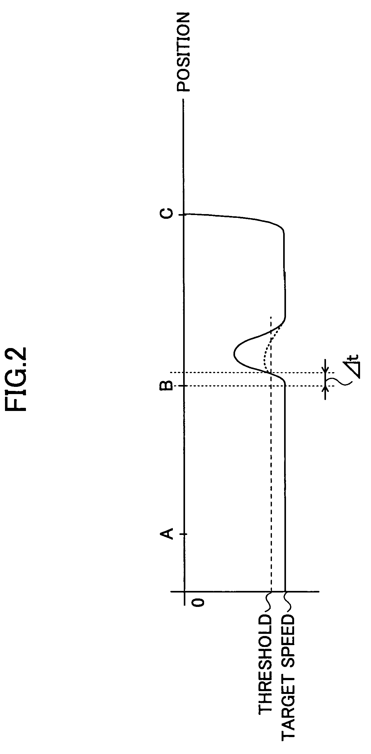
[0228]FIG. 12A is a cross-sectional view of a portion of the magnetic disk device 10 schematically showing a sequence of positions of the lift tab 21 in the operation of unloading the magnetic head 12 according to the present embodiment.

[0229]FIG. 12B is a graph showing correspondence of the integration of the BEMF (IntglBEMF) and the position thresholds Th1a...

third embodiment

[0238

[0239]The magnetic disk device of the present embodiment is basically the same as that of the first embodiment, except that in control of movement of an actuator when loading and unloading a magnetic head, instead of switching the bandwidth of PI control, a feed-forward control variable is superposed on a control variable of a feedback speed control system.

[0240]Below, the same reference numbers are used for the same elements as in the first embodiment.

[0241]FIG. 13 is a block diagram showing a configuration of a portion of a speed control system according to the third embodiment, which is capable of superposing a feed-forward control variable on a feedback control variable of a feedback speed control system.

[0242]FIG. 14A and FIG. 14B show tables containing data of the feed-forward control variable used in the operation of unloading the magnetic head 12, where, FIG. 14A shows a first table containing the feed-forward control variables used when the lift tab 21 comes into conta...


PUM

PropertyMeasurementUnit
floating heightaaaaaaaaaa
speedaaaaaaaaaa
distanceaaaaaaaaaa

Abstract

A storage device employing the ramp load / unload technique for an actuator is disclosed that has high shock-resistance, high vibration-resistance, and is capable of rapid and stable ramp load / unload operations. A position detection unit integrates the speed of the actuator, obtained by detecting a back electromotive force generated in a VCM, to calculate the present position of the magnetic head. A position determination unit compares the present position of the magnetic head with a series of position thresholds, and based on the comparison results, a bandwidth switching unit switches the bandwidth of a PI controller for feedback control of the actuator, from a narrow bandwidth to a wide bandwidth and vice versa. At positions where the speed starts to change or the speed change becomes small, the position determination is performed and the bandwidth is appropriately switched.

Description

BACKGROUND OF THE INVENTION[0001]1. Field of the Invention[0002]The present invention relates to a storage medium including an actuator employing a ramp loading / unloading technique, and a method of controlling movement of the actuator.[0003]2. Description of the Related Art[0004]In the recent years and continuing, technologies have been developed at an accelerating rate to increase recording density of storage media, such as hard disks, and the recording density per area is increasing by 100% annually. One subject in this development is to improve reproduction performance.[0005]In a hard disk, a magnetic head records or reproduces data in a magnetic disk while floating over the surface of the magnetic disk at a certain height. The amount of space between the magnetic head and the magnetic disk is called “floating height”, or “flying height”, or “head gap”. It is known that the reproduction performance improves when the floating height decreases, and as the state of the art of the te...

Claims


Application Information

Patent Timeline
Patent Type & Authority Patents(United States)
IPC IPC(8): G11B21/02G11B5/55G11B21/12G11B5/596
CPCG11B5/59605G11B5/5526
Inventor SUZUKI, NOBUYUKI
Owner KK TOSHIBA
Why Eureka
Try Eureka