

Scintillator, radiation detection apparatus, and manufacturing method thereof
- Summary
- Abstract
- Description
- Claims
- Application Information
AI Technical Summary
Benefits of technology
Problems solved by technology
Method used
Image

Examples
first embodiment
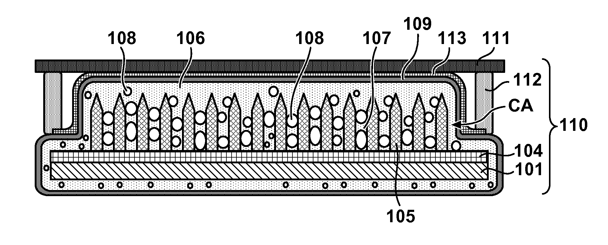
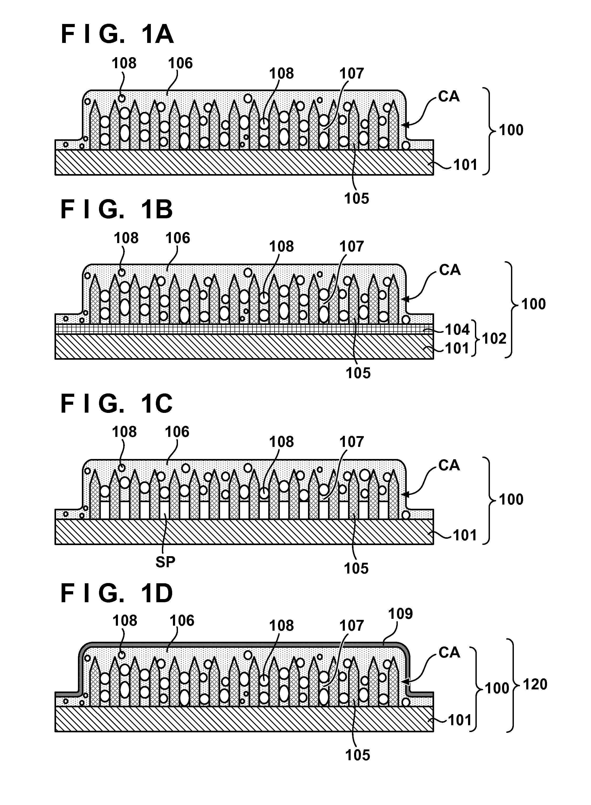
[0056]A method of manufacturing a scintillator 100 and a radiation detection apparatus 110 including it according to the first embodiment will be explained exemplarily. As exemplified in FIG. 4A, a two-dimensional array CA of columnar crystals 105 was formed on a support substrate 101 by vacuum deposition. When the columnar crystals 105 are made of CsI:Tl, they can be formed by co-deposition of CsI (cesium iodide) and TlI (thallium iodide). More specifically, columnar crystals could be formed by the following method. First, CsI and TlI were filled in a resistance heating boat, and the support substrate 101 was set on a rotating holder. Then, the interior of a deposition apparatus was evacuated by a vacuum pump, Ar gas was introduced to adjust the degree of vacuum to be 0.1 Pa, and then deposition was performed. As a result, the two-dimensional array CA of the columnar crystals 105 was formed on the support substrate 101. As the support substrate 101, a 1-mm thick amorphous carbon su...
second embodiment
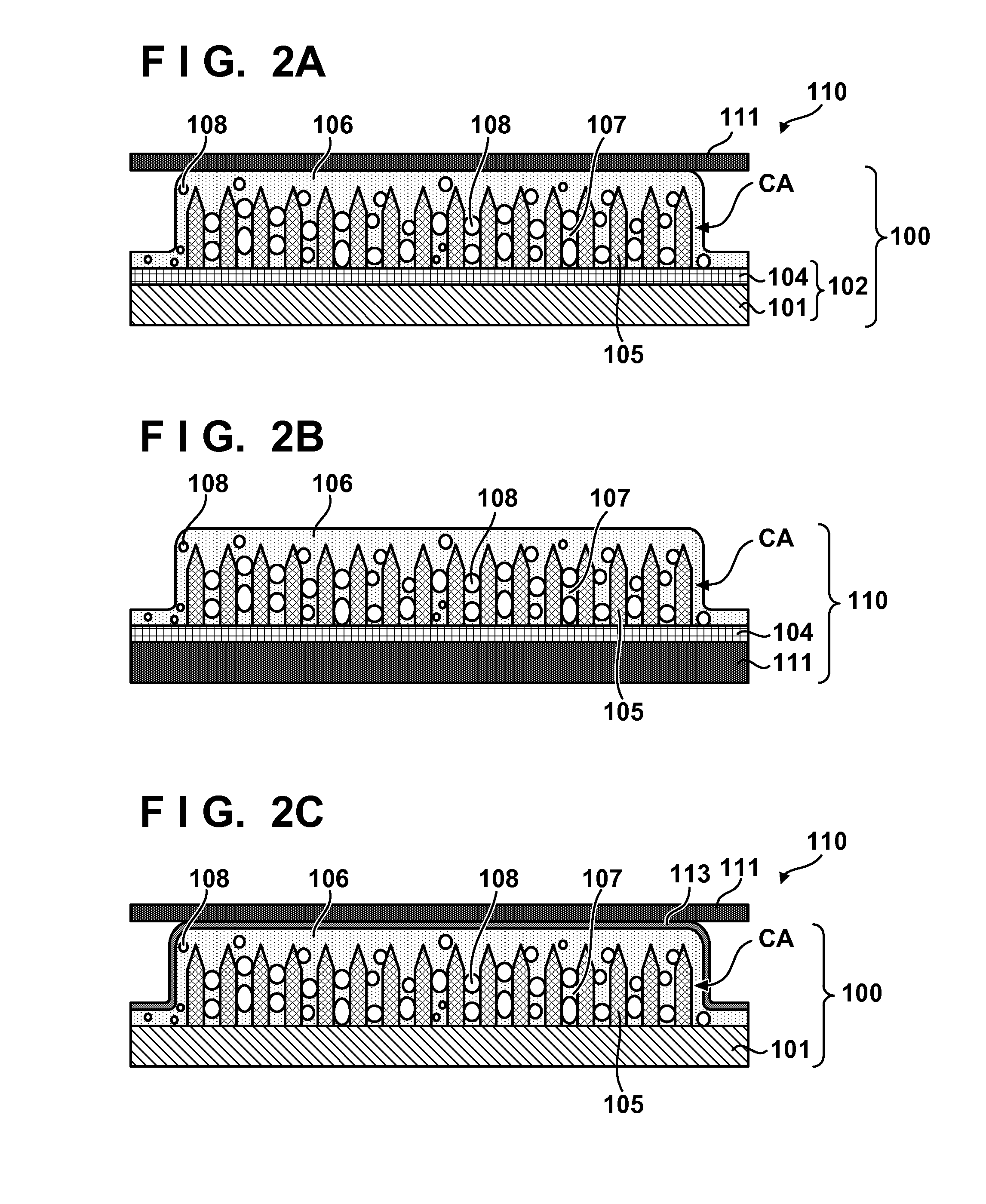
[0060]A method of manufacturing a radiation detection apparatus 110 according to the second embodiment will be explained exemplarily. In this example, to reduce the cost by simplifying the structure and process, the radiation detection apparatus 110 is fabricated by forming a two-dimensional array CA of columnar crystals 105 on a heat-resistant photoelectric conversion substrate 111, and forming a covering portion 106 on the resultant structure.
[0061]First, as exemplified in FIG. 5A, a two-dimensional array CA of columnar crystals 105 was formed on a photoelectric conversion substrate 111 by vacuum deposition. When the columnar crystals 105 are made of CsI:Tl, they can be formed by co-deposition of CsI (cesium iodide) and TlI (thallium iodide). More specifically, columnar crystals could be formed by the following method. First, CsI and TlI were filled in a resistance heating boat, and the photoelectric conversion substrate 111 having an undercoat layer 104 was set on a rotating hold...
third embodiment
[0063]A method of manufacturing a scintillator 100 and a radiation detection apparatus 110 including it according to the third embodiment will be explained exemplarily. In the third embodiment, a covering portion 106 including cavities 108 and connecting portions 107 is formed by thermally pressure-bonding a bubble-containing hot-melt resin to a two-dimensional array CA of columnar crystals 105, and making the heated hot-melt resin enter the gaps between the adjacent columnar crystals 105. The cavities 108 can be formed from bubbles in the hot-melt resin and bubbles which originally exist in the gaps between the adjacent columnar crystals 105.
[0064]First, as exemplified in FIG. 6A, a two-dimensional array CA of columnar crystals 105 was formed by the same method as that in the first embodiment on a support substrate 101 made of a 1-mm thick PEEK resin.
[0065]Then, as exemplified in FIG. 6B, a roll laminator having a heating / pressurization function was heated to 100° C., a bubble-cont...
PUM
 Abstract
Description
Claims
Application Information