Switch matrix for satellite payloads with multiple uplink beams and on-board signal processing

a satellite payload and switch matrix technology, applied in the field of switch matrixes, can solve the problems of not being able to provide point-to-multipoint connectivity, many designs are difficult to build out of smaller pieces in a modular manner, and the design is not suitable for satellite signals at microwave frequencies, so as to reduce spacecraft costs and avoid excessive signal losses

Inactive Publication Date: 2006-04-18
HUGHES ELECTRONICS
View PDF16 Cites 34 Cited by
  • Summary
  • Abstract
  • Description
  • Claims
  • Application Information

AI Technical Summary

Benefits of technology

[0011]The present invention provides a switch matrix that is suitable for use in a spacecraft environment. The present invention also provides a switch matrix that provides point-to-multipoint connectivity without excessive signal losses. The present invention also provides a switch matrix that provides ease of mechanical design and construction to reduce spacecraft costs.

Problems solved by technology

Typically, however, the amount of traffic in each uplink beam is either unknown beforehand or varies over time, and thus there must be some sort of switch matrix to reallocate and interconnect uplink beams to the on-board satellite processing resources.
Some of these designs are not suitable for satellite signals at microwave frequencies, because the related art switch matrix designs suffer from isolation problems at microwave frequencies.
Other switch matrices do not provide for point-to-multipoint connectivity without excessive signal losses caused by power splitting.
Many designs are also difficult to build out of smaller pieces in a modular manner.

Method used


Image

  • Switch matrix for satellite payloads with multiple uplink beams and on-board signal processing
  • Switch matrix for satellite payloads with multiple uplink beams and on-board signal processing
  • Switch matrix for satellite payloads with multiple uplink beams and on-board signal processing

Examples


Embodiment Construction

[0027]In the following description of the preferred embodiment, reference is made to the accompanying drawings which form a part hereof, and in which is shown by way of illustration a specific embodiment in which the invention may be practiced. It is to be understood that other embodiments may be utilized and structural changes may be made without departing from the scope of the present invention.

Overview of Related Art

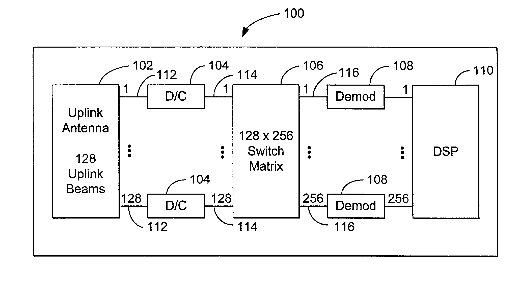
[0028]Switch matrices are commonly used in many satellite telecommunications systems designs to allow for redeployment of signals onboard the satellite. The switch matrix allows an input signal to be routed to any output desired through the use of crossbar switches or other types of switch matrices.

[0029]Some traditional switch matrix designs, such as the crossbar switch or the Clos switch matrix, were designed primarily for telephone switching networks, and are designed for point-to-point connectivity. Other switch matrices were designed for connections inside a comp...


PUM


Abstract

A method and apparatus for switching signals through a switch matrix are disclosed. The apparatus comprises an input module and an output module. The input module has a plurality of inputs typically equal to a number of cells in a reuse pattern, and the inputs receiving at least one uplink beam. The input module also has a plurality of outputs, the plurality of outputs is typically equal to the number of subbands in the uplink beam. The output module is coupled to the input module and selectively couples the outputs from the input module to an output of the output module. The method comprises the steps of grouping the uplink signals into a plurality of groups, the number of groups typically equal to a number of cells in the cell-based transmission matrix, where each group comprises a signal from each frequency used in the frequency reuse pattern. Each group of uplink signals is then separated into subband signals, which are then grouped together into groups of similar subband signals. The groups of similar subband signals are then forwarded to demodulators for processing within the satellite system.

Description

BACKGROUND OF THE INVENTION[0001]1. Field of the Invention[0002]This invention relates in general to switch matrices, and in particular to a switch matrix for satellite payloads with multiple uplink beams and on-board signal processing.[0003]2. Description of Related Art[0004]Communications satellites have become commonplace for use in many types of communications services, e.g., data transfer, voice communications, television spot beam coverage, and other data transfer applications. As such, satellites must provide signals to various geographic locations on the Earth's surface. As such, typical satellites use customized antenna designs to provide signal coverage for a particular country or geographic area.[0005]Many satellite payloads contain analog or digital signal processors. Analog processors are typically used to separate and combine different signals into specific channels (“channelize the signals”), and to switch different parts of the ground-to-satellite (“uplink”) signal t...

Claims


Application Information

Patent Timeline
Patent Type & Authority Patents(United States)
IPC IPC(8): H04H1/00B64G1/66H04B7/185H04H20/00
CPCH04B7/18515
Inventor TURLEY, PETER JOHNWU, SHIH-CHANG
Owner HUGHES ELECTRONICS
Why Eureka
Try Eureka