Layout of network using parallel and series elements

a network and series element technology, applied in the field of system, method and algorithm for layout of networks with parallel and series elements, can solve the problems of complex problem, difficulty in laying out physical networks, and difficulty in implementing networks using multiple identical elements, so as to reduce tedium, improve efficiency and consistency in network layout, and save time

Inactive Publication Date: 2006-04-18
TEXAS INSTR INC
View PDF11 Cites 2 Cited by
  • Summary
  • Abstract
  • Description
  • Claims
  • Application Information

AI Technical Summary

Benefits of technology

[0013]The invention provides several technical advantages including but not limited to increased efficiency and consistency in network layout, a reduction in tedium and savings in time. The potential for error in laying out a network is also reduced.

Problems solved by technology

In many engineering applications the problem of how to implement a network using multiple identical elements is encountered.
Problems arise however, in attempting to describe a network using a combination of series and parallel elements.
The problem is made more complex by concerns such as, in the example of integrated circuit and design, the desire to minimize area and the desire to minimize the count of individual network elements or to utilize elements of a particular value or size.
However, once a network has been described in terms of subnetworks of series and parallel elements, the task of laying out the physical network remains a challenging one.
Typically a designer spends long hours attempting to determine a layout for the subnetworks of individual elements and interconnections.
The task is complicated by the desirability of distributing elements of each subnetwork throughout the entire network to help alleviate the effects of unfavorable factors.
Such cut-and-try layout techniques are tedious, time consuming, and error prone.
Oftentimes network layouts have more than one hundred individual elements with the result that misplacement of elements detrimental to performance can go undetected.
The number of possible permutations and lack of a systematic approach can lead to inconsistency from designer to designer, which can lead to further complications in circuits having numerous network blocks prepared by numerous designers.

Method used


Image

  • Layout of network using parallel and series elements
  • Layout of network using parallel and series elements
  • Layout of network using parallel and series elements

Examples


Embodiment Construction

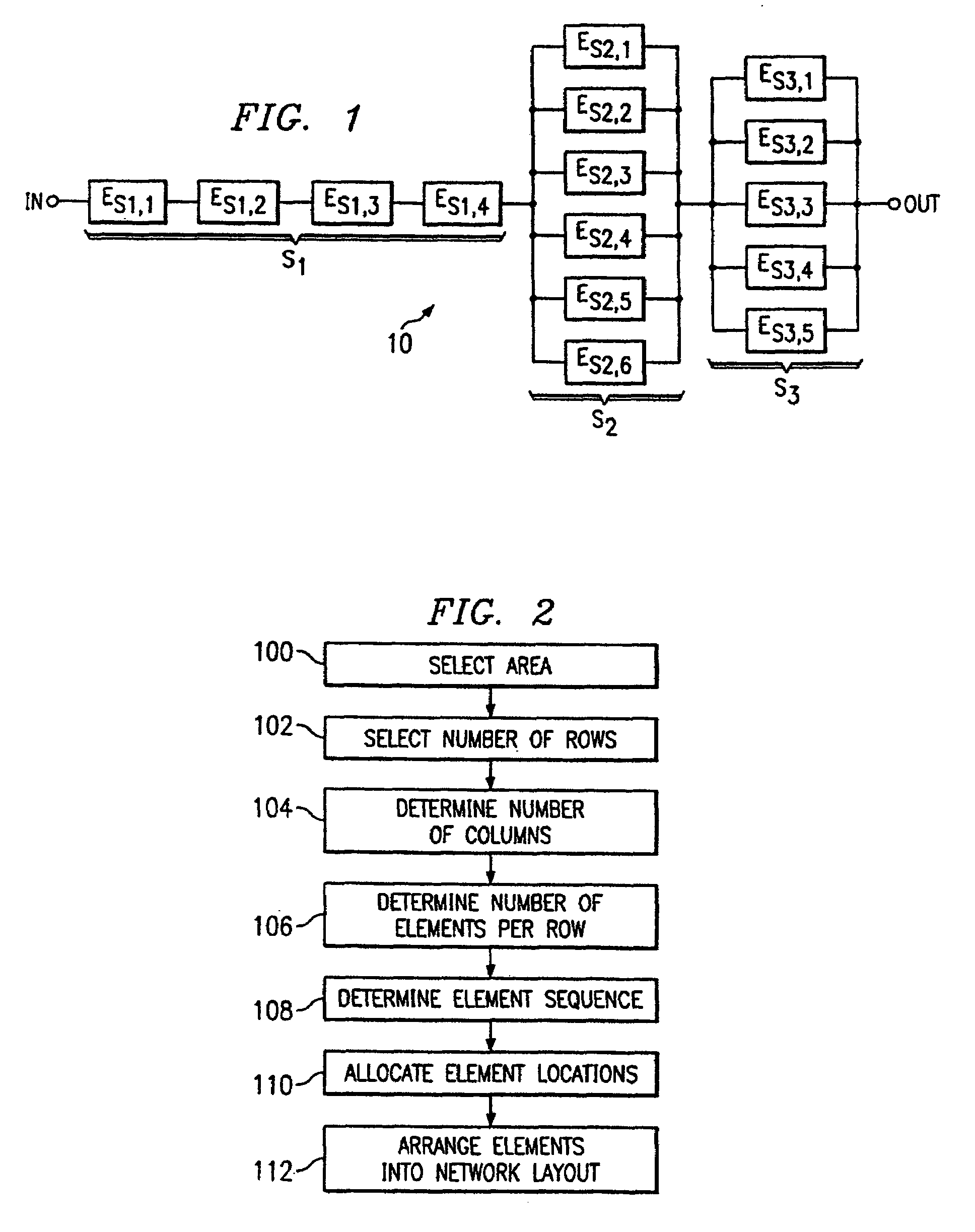
[0020]The invention provides for the systematic layout of a network in a combination of series and parallel elements. The invention may be used for networks which can be expressed in terms of a cross-quantity divided by a through-quantity such as, for example, an electronic network in which by Ohm's law, resistance is the quotient of voltage divided by current. Although for the sake of example the invention is described in terms of electronic resistor networks, it should be understood that the algorithms, methods, and systems described are applicable to other electrical and mechanical networks, such as a network of inductors, field effect or bipolar transistors, or fluid pumps, without departure from the concepts of the invention.

[0021]Given a particular network resistance value, there are a very large number of possible implementations using various numbers of various sizes of individual resistor elements. In the implementation of physical networks, engineering considerations narro...


PUM


Abstract

Disclosed are systems, methods, and algorithms for network layout. A network layout having subnetworks of matching series and parallel elements is systematically generated to implement the network within area constraints. After the selection of the number of rows of network elements, the number of elements in each row, the sequencing of the elements, and the element locations, are systematically determined. The network layout systematically produced reduces the influence of unfavorable factors on the network such as temperature gradients, process gradients, and interference, by dispersing subnetwork elements throughout the layout.

Description

[0001]This application is a division of Ser. No. 10 / 211,833, filed Aug. 3, 2002 now U.S. Pat. No. 6,848,092.RELATED APPLICATION[0002]U.S. patent application of Du and Jaska, Ser. No. 10 / 217,285, filed Aug. 12, 2002, entitled “Implementation of Networks Using Parallel and Series Elements,” now U.S. Pat. No. 6,751,784, is incorporated herein in its entirety for all purposed by this reference.TECHNICAL FIELD[0003]The present invention relates in general to systems, methods, and algorithms for layout of networks with parallel and series elements. More particularly, the invention relates to the systematic generation of a schematic or design layout for a network using combinations of matching series and parallel elements.BACKGROUND OF THE INVENTION[0004]In a network (M) which may be characterized by the quotient of a cross-quantity and a through-quantity, M=cross-quantity / through-quantity, it is generally known that certain relationships govern series and parallel network elements. For ex...

Claims


Application Information

Patent Timeline
Patent Type & Authority Patents(United States)
IPC IPC(8): G06F17/50
CPCG06F17/5068G06F17/509G06F2217/78G06F30/18G06F30/39G06F2119/06
Inventor JASKA, DAVIDDU, TAN
Owner TEXAS INSTR INC
Why Eureka
Try Eureka