Self-piercing fastening system

a fastening system and self-piercing technology, applied in the direction of threaded fasteners, screwdrivers, manufacturing tools, etc., can solve the problems of vehicle exhaust and other debris moving, adding an expensive extra manufacturing step and complexity to the setting tool, and creating vehicle noise and vibration at the join

Active Publication Date: 2006-04-25
NEWFREY
View PDF90 Cites 55 Cited by
  • Summary
  • Abstract
  • Description
  • Claims
  • Application Information

AI Technical Summary

Benefits of technology

[0006]The fastening system of the present invention is advantageous over conventional devices in that a joint between a workpiece and a fastener is created which prevents the passage of dirt, debris and exhaust through the joint area. Another advantage of the present invention is the real-time controllability, changes, and accuracy of the insertion machine used to set the fastener, realized through use of the electromagnetic actuator, a real-time sensing system and control logic. This improves automatic fastening characteristic recognition, quality, flexibility and result tracking. Machine and processing costs and complexity are additionally reduced through the self-piercing nature of the fastener and process. Moreover, the fastening system of the present invention is advantageously suitable for use in creating a two-way joint; the clinching section of the fastener joins two or more sheet metal panels while the body of the fastener also secures a component such as an electrical connector, trim panel and / or a circuit board. Additional features and benefits will be further disclosed hereinafter with reference to the appended claims and accompanying drawings.
is the real-time controllability, changes, and accuracy of the insertion machine used to set the fastener, realized through use of the electromagnetic actuator, a real-time sensing system and control logic. This improves automatic fastening characteristic recognition, quality, flexibility and result tracking. Machine and processing costs and complexity are additionally reduced through the self-piercing nature of the fastener and process. Moreover, the fastening system of the present invention is advantageously suitable for use in creating a two-way joint; the clinching section of the fastener joins two or more sheet metal panels while the body of the fastener also secures a component such as an electrical connector, trim panel and / or a circuit board. Additional features and benefits will be further disclosed hereinafter with reference to the appended claims and accompanying drawings.

Problems solved by technology

This is disadvantageous in that dirt, vehicle exhaust and other debris can move from one side of the panel to the other through the hole.
Furthermore, other traditional clinch nuts and clinch studs employ a pre-pierced panel opening, prior to insertion of the nut or stud, which adds an expensive extra manufacturing step and complexity to the setting tool, as well as adds undesirable additional tolerance variations which may lead to the creation of vehicle noise and vibration at the joint.

Method used


Image

  • Self-piercing fastening system
  • Self-piercing fastening system
  • Self-piercing fastening system

Examples


Embodiment Construction

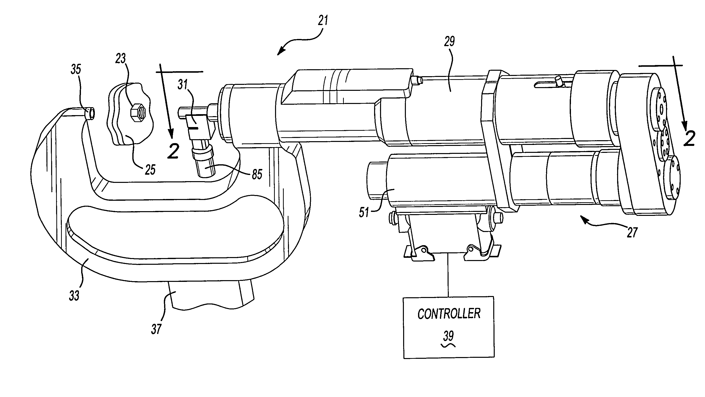
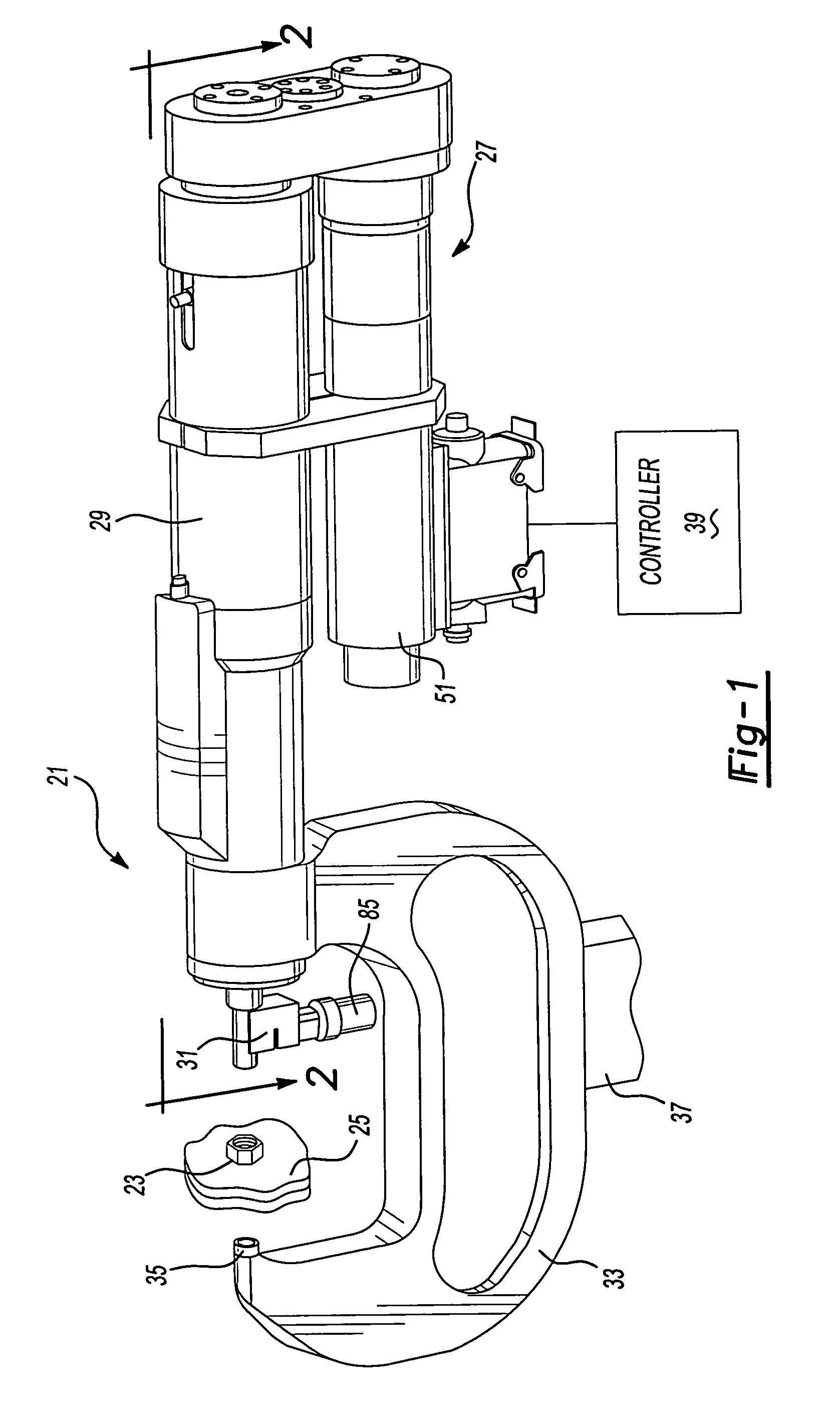
[0018]Referring to FIGS. 1–3, the preferred embodiment of a fastening system 21 of the present invention includes a fastener 23, a pair of sheet metal workpieces 25 and an installation machine 27. Machine 27 has a set of outer housings 29, a receiver assembly or nose piece 31, a C-frame 33 and a stationary die 35 mounted to the C-frame. An arm of an articulating robot 37 is preferably mounted to C-frame 33 but may be alternately mounted to housing 29. A computer controller 39 is connected to machine 27 and includes a programmable microprocessor, memory, an input device such as a keyboard or touch-screen, and an output device such as a display screen, CRT, display lights or the like.

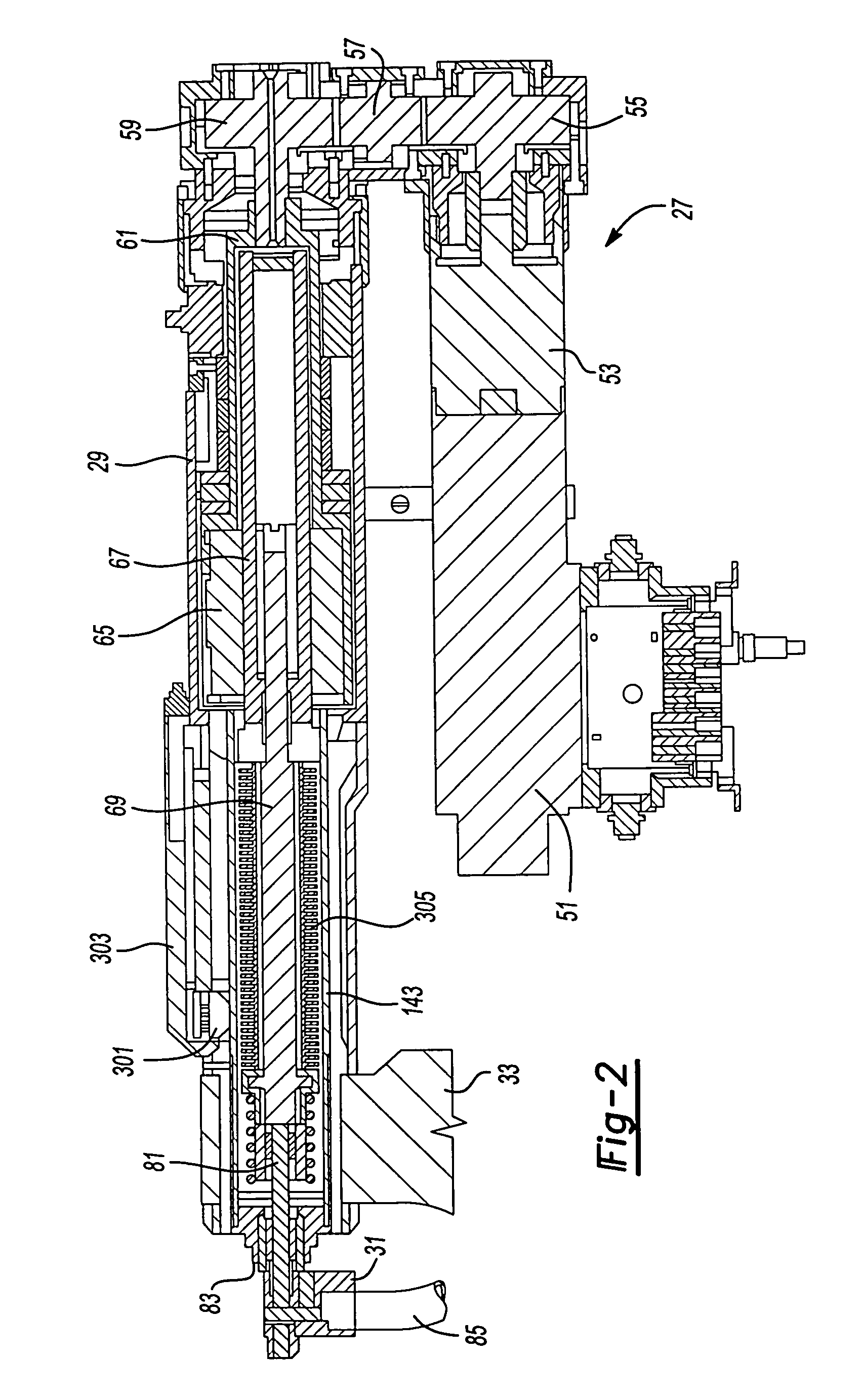
[0019]An electric motor 51 has an internal armature which rotates when electromagnetically energized. The armature operably causes rotation of an output shaft, which in turn, rotates a set of two or three reduction, spur gears 55, 57 and 59. Spur gear 59 thereby rotates a nut housing 61 which is coupled t...


PUM

PropertyMeasurementUnit
sizeaaaaaaaaaa
fastener insertion forceaaaaaaaaaa
insertion speedaaaaaaaaaa

Abstract

The preferred embodiment of a fastening system includes a self-piercing fastener having a thread-like pattern. In another aspect of the present invention, a fastener insertion machine employs an electromagnetic actuator without fluid actuation. A further aspect of the present invention uses a rotary-to-linear transmission within the machine to advance the fastener. In still another aspect of the present invention a self-piercing fastener is a clinch nut or a clinch stud.

Description

CROSS REFERENCE TO RELATED APPLICATIONS[0001]This application claims priority to Provisional Application U.S. Ser. No. 60 / 524,360, filed Nov. 21, 2003, which is incorporated by reference herein.BACKGROUND OF THE INVENTION[0002]The present invention generally relates to fastening systems and more particularly pertains to a self-piercing, threaded fastener, joint and machine.[0003]It has recently become known to employ hydraulic and electric motor actuated machines to insert self-piercing rivets into sheet metal panels. For example, an electric motor-based device is disclosed in U.S. Pat. No. 6,276,050 entitled “Riveting System and Process for Forming a Riveted Joint,” which issued to Mauer et al. on Aug. 21, 2001; this patent is incorporated by reference herein.[0004]A conventional clinch nut has also been employed for use with a single thickness, sheet metal, automotive panel. A slug is pierced from the panel by the nut and a ram of a setting machine thereafter removes the slug. Thu...

Claims


Application Information

Patent Timeline
Patent Type & Authority Patents(United States)
IPC IPC(8): B23P21/00B21J15/14B21J15/02B21J15/10B21J15/16B21J15/32B23P19/06F16B37/06
CPCB21J15/025F16B37/062B23P19/062Y10T29/5377Y10T29/53039Y10T29/49771Y10T403/4933Y10T403/4974Y10T29/49954Y10T29/49956Y10T29/5307Y10T403/4966Y10T29/49835Y10T29/5343Y10T29/53052Y10T29/53061Y10T29/53065Y10T29/49915
Inventor ZDRAVKOVIC, SRECKORAMASAMY, SIVAKUMAR
Owner NEWFREY
Why Eureka
Try Eureka