Thermally-controlled valves and methods of using the same in a wellbore

a technology of thermal control valve and wellbore, which is applied in the direction of wellbore/well accessories, insulation, instruments, etc., can solve the problems of difficult recovery of oil from subterranean formations, high temperature gradient along the wellbore, and areas that are hotter and colder, so as to achieve easy transportation and reduce the viscosity of oil.

Inactive Publication Date: 2006-04-25
HALLIBURTON ENERGY SERVICES INC
View PDF42 Cites 110 Cited by
  • Summary
  • Abstract
  • Description
  • Claims
  • Application Information

AI Technical Summary

Benefits of technology

[0006]According to an embodiment, methods are provided for servicing a wellbore by using a thermally-controlled tool in a wellbore, for example, a steam assisted gravity drainage (SAGD) wellbore. The thermally-controlled tool comprises a thermally-controlled valve (TCV) for controlling the flow of material into, out of, or through the wellbore. A plurality of TCV's may be arranged in the wellbore to control the injection of steam into the wellbore. The steam injected into the wellbore heats oil in an adjacent subterranean zone, thereby decreasing the viscosity of the oil. As a result, the oil can be more easily conveyed from the subterranean zone to the surface of the earth during production of the oil. In another embodiment, a plurality of TCV's are arranged in a production conduit disposed in the wellbore to control the recovery of material from the wellbore. The TCV's may restrict the flow of steam out of the wellbore.

Problems solved by technology

Many reservoirs containing vast quantities of oil have been discovered in subterranean formations; however, the recovery of oil from subterranean formations has been very difficult due to the relatively high viscosity of the oil and / or the presence of viscous tar sands in the formations.
However, the steam typically is not evenly distributed throughout the wellbore, resulting in a temperature gradient along the wellbore.
As such, areas that are hotter and colder than other areas of the wellbore, i.e., hot spots and cold spots, undesirably form in the wellbore.
The cold spots lead to the formation of pockets of oil that remain immobile.
Consequently, the steam bypasses a large portion of the oil residing in the formation, and thus fails to heat and mobilize the oil.

Method used


Image

  • Thermally-controlled valves and methods of using the same in a wellbore
  • Thermally-controlled valves and methods of using the same in a wellbore
  • Thermally-controlled valves and methods of using the same in a wellbore

Examples


Embodiment Construction

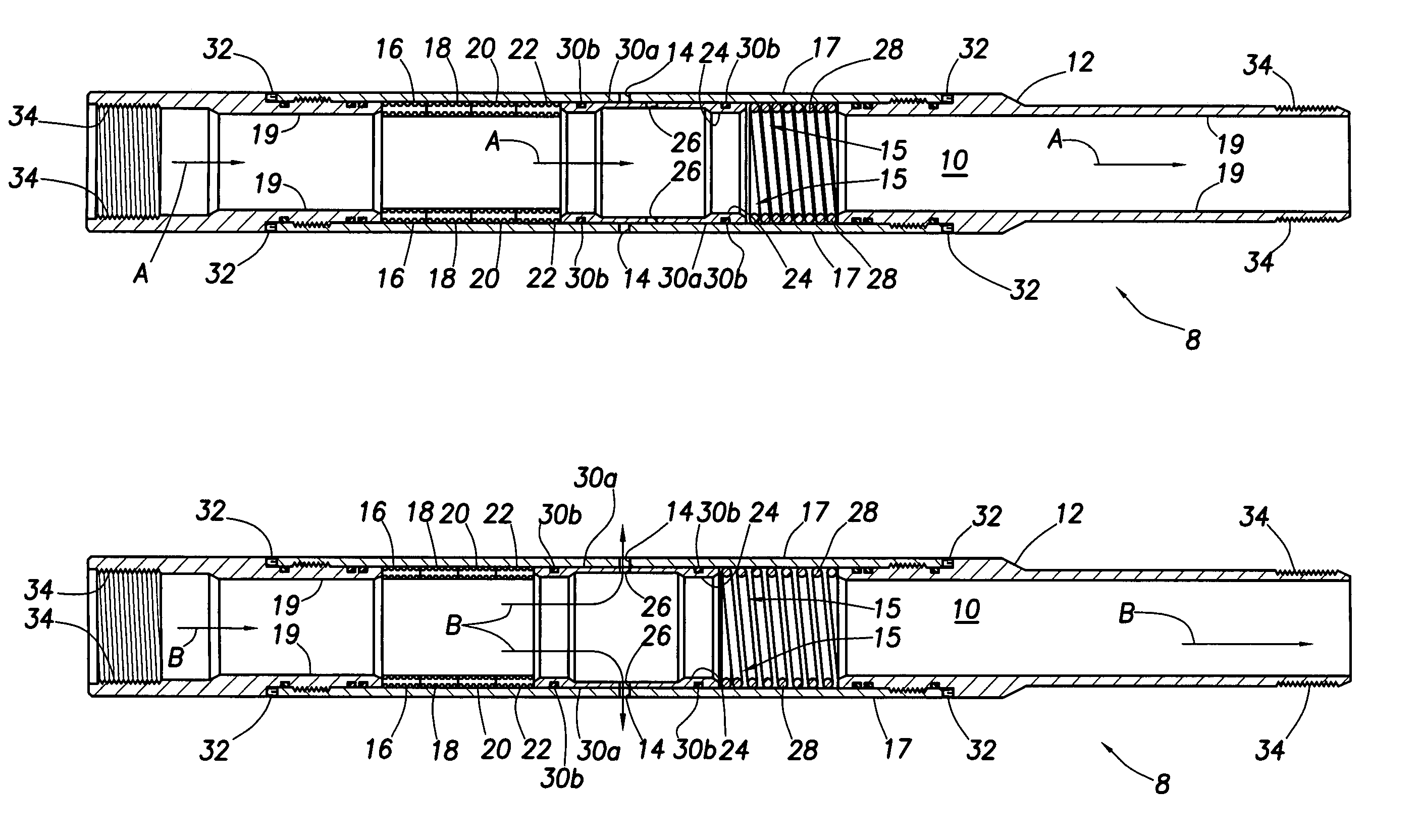
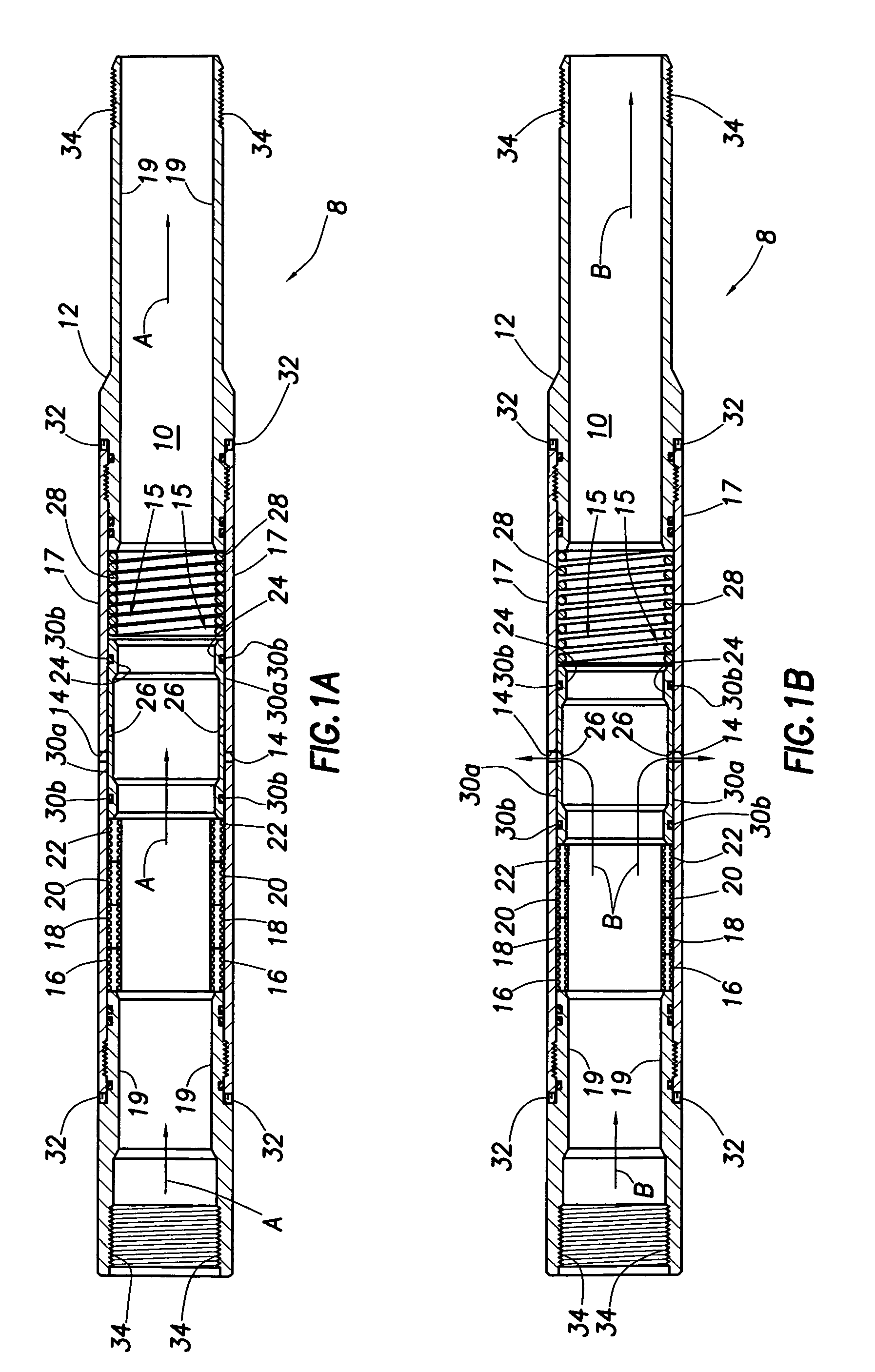
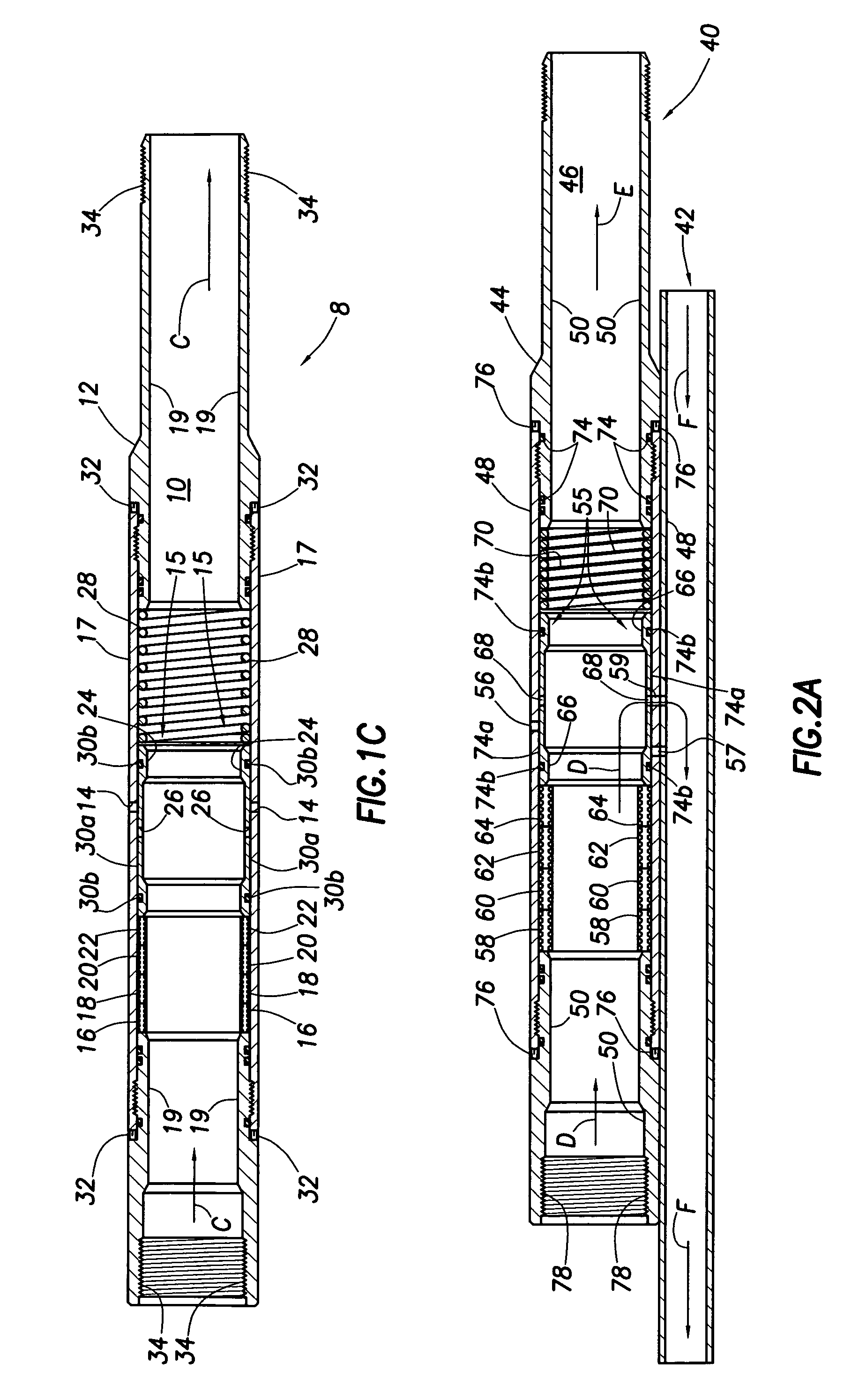
[0020]As used herein, a thermally-controlled downhole tool is defined as controlling a function of a tool disposed in a wellbore between first and second positions and intermediate positions therebetween, and vice versa, in response to changes in temperature. A control means is disposed downhole in situ with the tool. For example, controlling and / or sensing elements may be integral with the tool and thus may be contained within a tool housing. Also, the sensing and controlling elements may be separate or combined. The thermally-controlled tool may comprise a thermally-controlled valve (TCV) for controlling the production and / or injection of material such as steam downhole. The TCV is described in more detail below.

[0021]In an embodiment, a control signal is not transmitted from the surface. The temperature change is sensed downhole by the thermally-controlled tool, and the function of the tool is self-controlled accordingly. For example, the control element may comprise a mechanical...


PUM


Abstract

Methods of operating a downhole tool comprise thermally-controlling the tool by sensing a temperature and controlling the tool in response to the sensed temperature. Thermally-controlled downhole tools comprise a control element responsive to a change in temperature that control flow into, out of, or through a wellbore. Methods and systems for servicing a wellbore comprise using a thermally-controlled tool comprising a thermally-controlled valve (TCV) in a wellbore. The TCV includes a valve body comprising an injection port for allowing material to flow into or out of the wellbore and an opening / closing mechanism for regulating flow of the material through the injection port in response to a change in temperature. The valve body may be coupled to a downhole conduit. A plurality of TCV's may be arranged in the wellbore to control the injection of steam into the wellbore or the recovery of oil from the wellbore.

Description

CROSS-REFERENCE TO RELATED APPLICATIONS[0001]This application is related to commonly owned U.S. patent application Ser. No. 10 / 680,901, entitled “Loop Systems And Methods Of Using The Same For Conveying and Distributing Thermal Energy Into A Wellbore,” filed on Oct. 6, 2003 and incorporated by reference herein.FIELD OF THE INVENTION[0002]This invention generally relates to the production of oil. More specifically, the invention relates to methods of using a thermally-controlled valve in a wellbore to regulate the flow of fluid such as steam into and out of the wellbore.BACKGROUND OF THE INVENTION[0003]Many reservoirs containing vast quantities of oil have been discovered in subterranean formations; however, the recovery of oil from subterranean formations has been very difficult due to the relatively high viscosity of the oil and / or the presence of viscous tar sands in the formations. In particular, when a production well is drilled into a subterranean formation to recover oil resid...

Claims


Application Information

Patent Timeline
Patent Type & Authority Patents(United States)
IPC IPC(8): E21B43/00E21B34/08E21B43/24G05D23/08G05D23/12
CPCE21B34/08G05D23/123G05D23/08E21B43/24
Inventor STEELE, DAVID JOEBAYH, III, RUSSELL IRVINGPARLIN, JOSEPH D.MEADERS, MICHAEL WADESAURER, DAN P.
Owner HALLIBURTON ENERGY SERVICES INC
Why Eureka
Try Eureka