Prosthetic heart valve system

a heart valve and prosthesis technology, applied in the field of prosthetic heart valve systems, can solve the problems of inconvenient operation, inconvenient operation, and inability to extend the stent post undetectedly, and achieve the effect of reducing the risk of surgery, and reducing the surgical efficiency of surgeons

Inactive Publication Date: 2006-04-25
MEDTRONIC INC
View PDF63 Cites 122 Cited by
  • Summary
  • Abstract
  • Description
  • Claims
  • Application Information

AI Technical Summary

Benefits of technology

[0013]Another aspect of the present invention relates to a prosthetic heart valve system including a prosthetic heart valve, a deflection device, and a holder. The deflection device includes a tensioning component coupled to the prosthetic heart valve, preferably by a line. The holder includes a holder body coupled to the prosth

Problems solved by technology

Implantation of a prosthetic heart valve presents numerous technical challenges, regardless of the prosthesis' configuration.
Due to a lack of visibility through the prosthetic valve, a surgeon can inadvertently loop sutures around the stent posts during suturing of the annular suture ring portion of the prosthesis.
Similarly, the extending stent posts may undesirably “snag” on chordae or trabeculae inside the left ventricular cavity.
In particular, with aortic heart valve implantation, a surgeon is often faced with little room to maneuver.
Thus, while the concern for “snagging” of the stent posts (i.e., inadvertently looping sutures about stent post(s)) is minimal during aortic prosthetic heart valve implantation, the proximally extending stent posts associated with the stented prosthesis interfere with the various other maneuvers required of the surgeon.
Unfortunately, the above-described mitral prosthetic heart valve holders are of little value for aortic valve replacement procedures in that the holder positions the handle to extend in a direction opposite that of the stent posts.
Without this handle component, the holder cannot

Method used


Image

  • Prosthetic heart valve system
  • Prosthetic heart valve system
  • Prosthetic heart valve system

Examples


Embodiment Construction

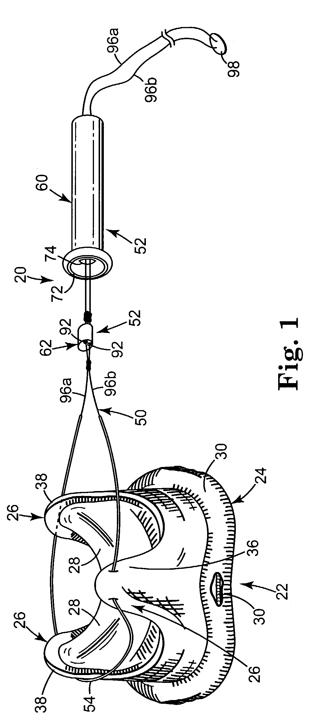
[0046]One preferred embodiment of a deflection device 20 in combination with a prosthetic heart valve 22 is shown in FIG. 1. As a point of reference, the prosthetic heart valve 22 can assume a wide variety of forms (e.g., bioprosthetic heart valve having tissue leaflets or a synthetic heart valve having polymeric leaflets), and can be specifically configured for replacing any heart valve. In general terms, however, the prosthetic heart valve 22 includes a stent 24, forming stent posts 26, and leaflets 28. As is known in the art, the stent 24 provides a support framework for the prosthetic heart valve 22 and further includes an inner frame member or stent ring 30 (shown partially in FIG. 1) encompassed by a cover 32 that otherwise serves as a sewing or suturing annulus or flange. The stent posts 26 extend from the stent ring 30, and each are preferably composed of an internal frame structure (not shown) encompassed by a cloth covering 36. Each of the stent posts 26 terminates in a fr...


PUM


Abstract

A prosthetic heart valve system including a prosthetic heart valve and a deflection device. The deflection device includes a line and a connector assembly including a tensioning component. The line interconnects and passes through free ends of stent posts associated with the heart valve, and is further connected to the tensioning component. The tensioning component is transitionable to a tensioning state in which the line is tensioned to inwardly deflect the stent posts. In this regard, the tensioning component is self-locking relative to the line in the tensioning state, and an entirety of the line extending distal the tensioning device does not extend beyond a stent portion of the heart valve opposite the stent posts. In a preferred embodiment, a holder body is further included, coupled to the heart valve apart from the deflection device.

Description

CROSS-REFERENCE TO RELATED APPLICATIONS[0001]This application claims priority to, and is entitled to the benefit of, U.S. Provisional Patent Application Ser. No. 60 / 345,297, filed Jan. 2, 2002, and U.S. patent application Ser. No. 10 / 131,933, filed Apr. 25, 2002, the teachings of all of which are incorporated herein by reference.BACKGROUND OF THE INVENTION[0002]The present invention relates to implantable prosthetic heart valves with flexible leaflets. More particularly, it relates to a prosthetic heart valve system including a device for effectuating prosthetic heart valve stent post deflection during implantation thereof.[0003]Various types and configurations of prosthetic heart valves, used to replace diseased natural human heart valves, are known in the art. The actual shape and configuration of any particular prosthetic heart valve is, of course, dependent to some extent upon the valve being replaced (i.e., mitral valve, tricuspid valve, aortic valve, and pulmonary valve). In g...

Claims


Application Information

Patent Timeline
IPC IPC(8): A61F2/24
CPCA61F2/2412A61F2/2439A61F2/2427A61F2/2418
Inventor JOHNSON, KEITH M.LEMMON, JACK D.MORROW, JOSEPH C.RYAN, TIMOTHY R.
Owner MEDTRONIC INC
Why Eureka
Try Eureka