Electromagnetic motor

a technology of electric motor and motor body, applied in the direction of motor/generator/converter stopper, dynamo-electric gear control, motor/generator/converter stopper, etc., can solve the problems of difficult bulk handling and impracticality of brushless dc motor fabrication, and achieve the effect of producing more torqu

Inactive Publication Date: 2006-04-25
PRATT & WHITNEY POWER SYST
View PDF8 Cites 24 Cited by
  • Summary
  • Abstract
  • Description
  • Claims
  • Application Information

AI Technical Summary

Benefits of technology

[0023]The electric motor of the present invention shares features with the brushless DC motor in every respect with one critical exception: the usual permanent magnet rotor is replaced with an electromagnetic wound rotor. Even with the most advance PM (Permanent Magnet) neodymium “super magnet” material, flux density within the brushless DC motor is only half the flux capacity of iron rather than near saturation as achieved by the motor of the present invention which effectively doubles iron utilization.
[0024]Maximum flux density in the motor of the present invention allows doubling of torque per unit of heat generation relative to a brushless DC motor. In other words, torque may be produced with less than a fourth of the energy losses. Power density is over twice as great for a given heat dissipation with a corresponding increase in motor efficiency.
[0026]The motor of the present invention also has features common to the DC motor. Both operate at full flux density and 90° torque angle. The most obvious difference is elimination of mechanical commutation (brushes and commutator) which enables the motor of the present invention to run many times faster with a commensurate increase in shaft power. Unlike the brush-type DC motor, the rotor-stator gap is uniform without salient poles thereby eliminating flux distortion and the necessity of corrective inter-poles. Moreover, total armature copper is continuously excited for greater efficiency than a standard brush-type DC motor where only partial copper is available for toque production at any instant.AC Induction Motor:
[0028]A relatively large rotor-stator gap is employed in the motor of the present invention to prevent core saturation at the current (amp-turns) levels required for useful torque production. The air gap may be increased 10–20 times over that typically found in a standard AC induction motor.
[0030]Capable of full flux density at high rpm, along with an ideal 90° torque angle, no conceivable motor can produce more torque more efficiently The design of the motor of the present invention advances motor technology to the ultimate theoretical limits established by the laws of physics.

Problems solved by technology

Furthermore, difficulty in handling bulk quantities of PM material makes fabrication of larger brushless DC motor sizes impracticable.

Method used


Image

  • Electromagnetic motor
  • Electromagnetic motor
  • Electromagnetic motor

Examples


Embodiment Construction

Motor Operation

Electromagnetic Symmetry:

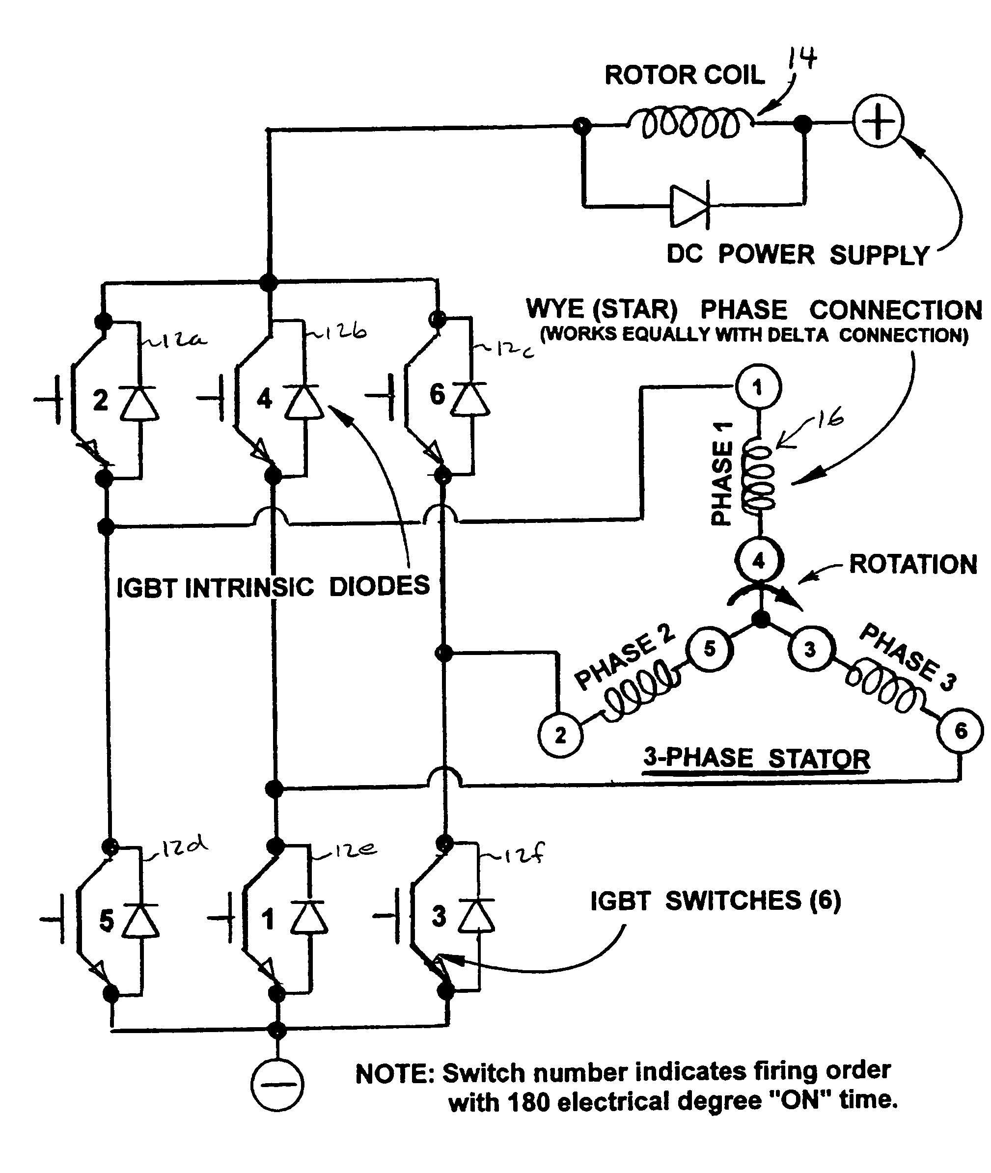
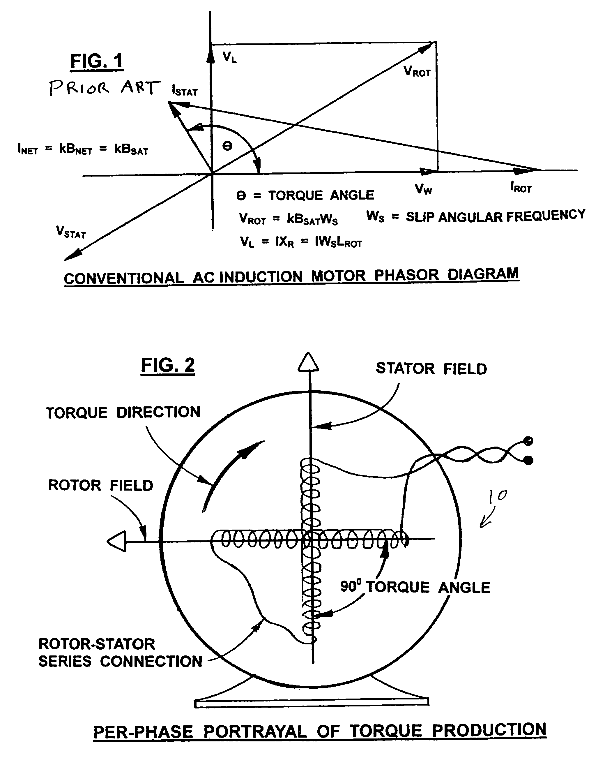
[0043]Referring to FIG. 2, the rotor and stator in the motor 10 of the present invention are not linked solely magnetically as in the transformer model of the AC induction motor. Instead, the wound rotor coil and stator coil are connected electrically in series which assures precise coordination of their magnetic fields relative to one another at a 90° torque angle.

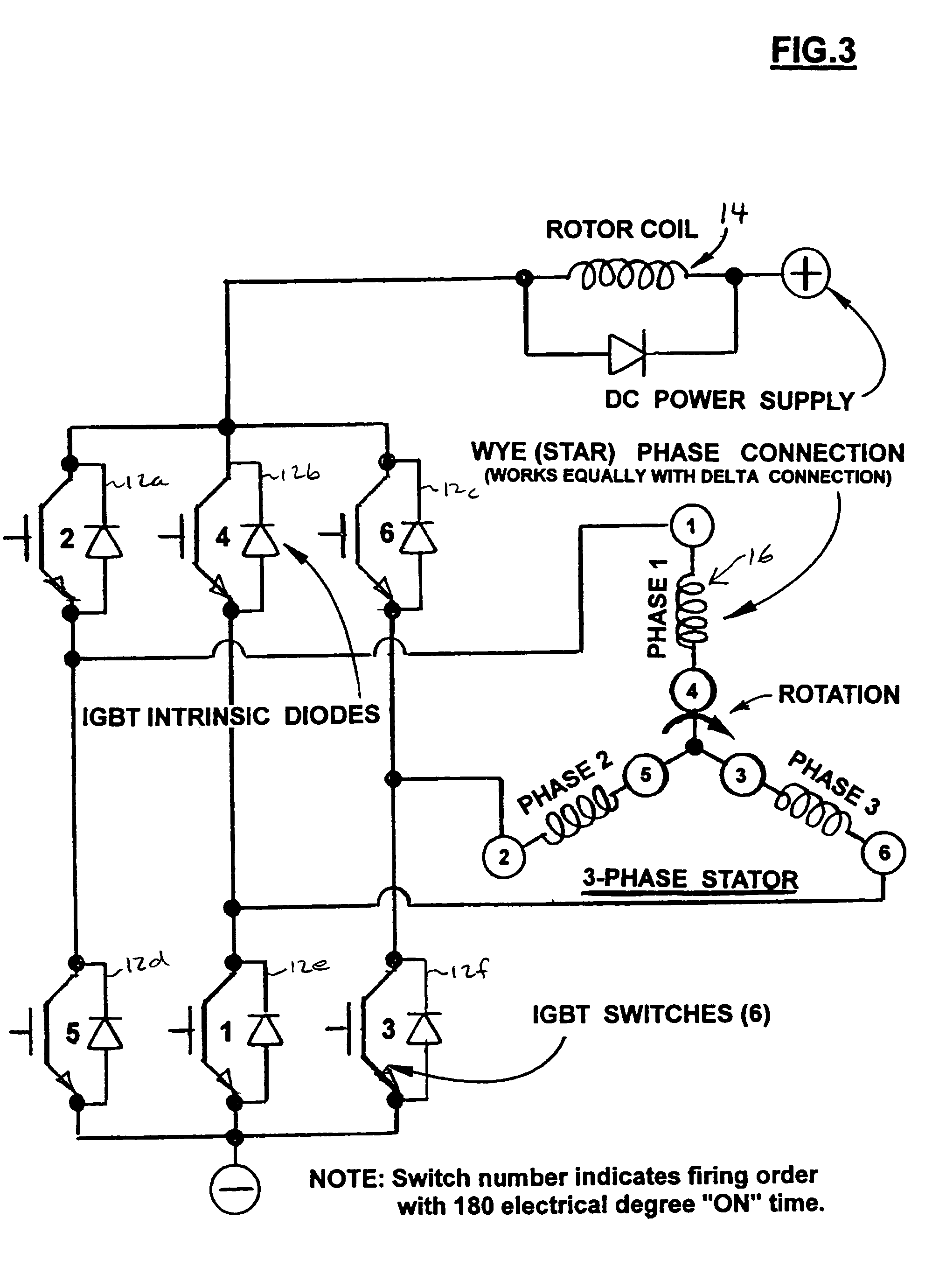
[0044]The motor 10 incorporates a rotor and stator that are electromagnetically identical. Each has the same amp-turns and magnetic circuit reluctance Connected in series, they both produce fields of equal magnitude at controlled angular alignment so that peak magnetic fields are synchronized at an orientation of 90°. Optimum torque angle of 90° is thereby maintained under all operating conditions of speed and torque. With the same amp-turns and same magnetic field, it is impossible to distinguish rotor from stator except that one rotates and the other is stationary.

Enlarged Air Gap...


PUM


Abstract

An electromagnetic motor with increased torque. The motor has a rotor coil configured to generate a magnetic field. At least two stator coils are connected in series with the rotor coil. Each of the stator coils is configured to generate a respective magnetic field. The motor further includes a plurality of switches configured to generate the magnetic field in each of the respective rotor and stator coils. The switches are configured to generate the magnetic field in the stator coils such that the rotor coil rotates in response thereto. By having the rotor and stator coils connected in series, the torque of the motor is increased.

Description

RELATED APPLICATION[0001]This application claims the benefit of U.S. Provisional Application No. 60 / 508,438, filed Oct. 3, 2003, the contents of which are incorporated by reference herein.BACKGROUND OF THE INVENTION[0002]Three main motor types dominate today's motor market: 1) AC Induction motor; 2) Brush-type DC motor; 3) Brushless DC motor. Each of these will be discussed in some detail to highlight distinctive characteristics of the DC motor of the present invention.AC Induction Motor:[0003]The AC induction motor may be modeled essentially as a rotating transformer where the primary coil represents the stator and the rotor serves as the secondary coil comprising one turn. Acting as a transformer, rotor (secondary) current is the result of voltage induced by a changing magnetic field created by the stator (primary). Stator and rotor are linked magnetically by an iron core (magnetic circuit) that conducts magnetic flux through both the rotor and stator windings. Ideally this magnet...

Claims


Application Information

Patent Timeline
Patent Type & Authority Patents(United States)
IPC IPC(8): H02P1/42H02K11/00H02P6/00H02P25/16
CPCH02K57/006H02P25/16H02P6/00H02K11/00H02P2201/05H02K99/20H02K19/12H02K29/00H02P6/32
Inventor KERLIN, IV, JOHN HARNSWORTHSANDBERG, KORTNEY
Owner PRATT & WHITNEY POWER SYST
Why Eureka
Try Eureka