
Tunable filters having variable bandwidth and variable delay

a variable bandwidth and delay technology, applied in waveguide devices, amplifiers, amplifier modifications to reduce non-linear distortion, etc., can solve the problems of signal generation of harmonics and subharmonics, low power handling capability, and rapid degradation of the q factor of these varactors

Inactive Publication Date: 2006-04-25
NXP USA INC
View PDF32 Cites 20 Cited by
  • Summary
  • Abstract
  • Description
  • Claims
  • Application Information

AI Technical Summary

Benefits of technology

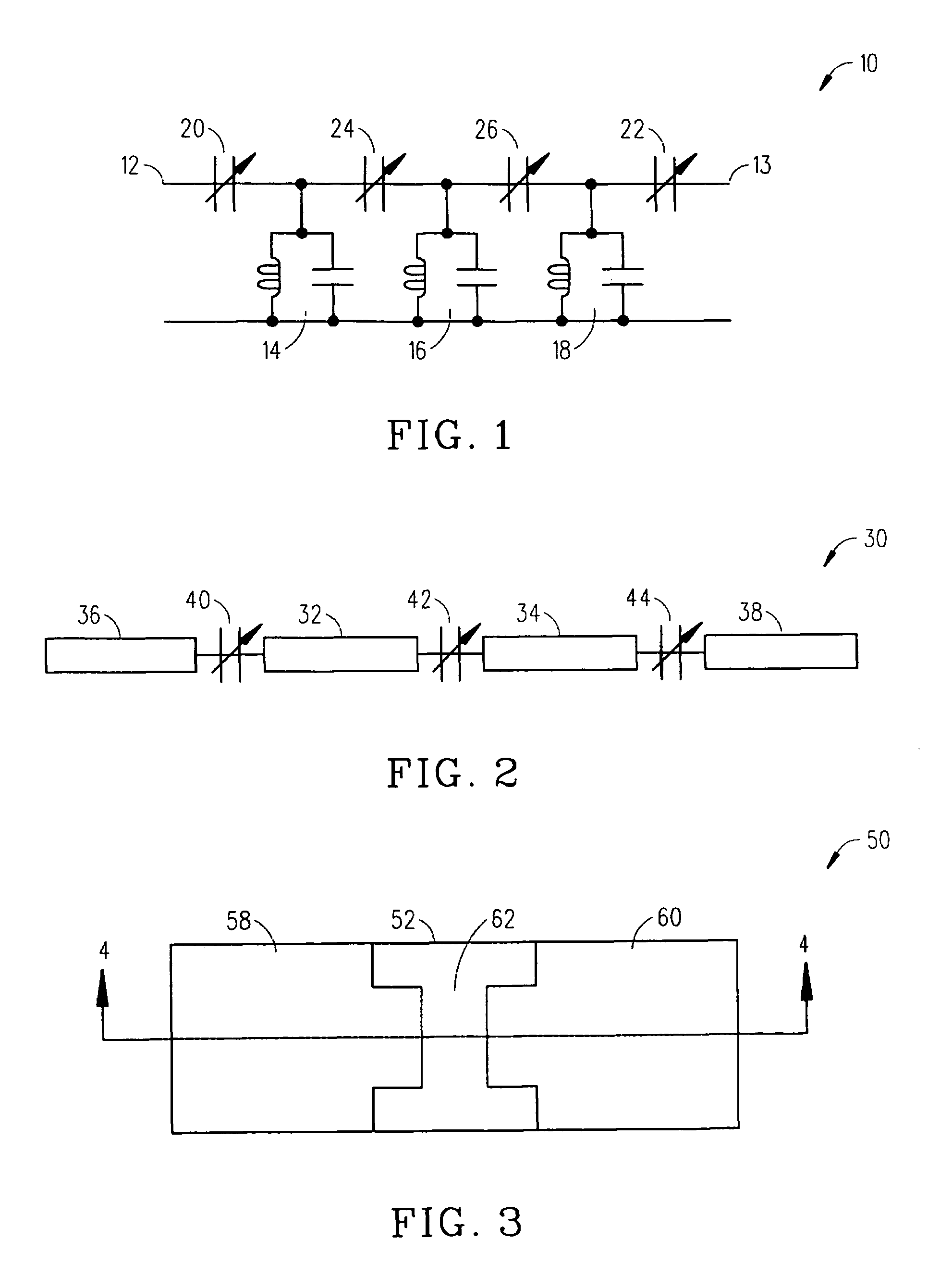
[0016]Changing the capacitance of the tunable bandpass filters also changes the delay of signals passing through the filters. This makes the filters suitable for use in devices requiring a tunable delay function. Thus the invention also encompasses the use of such filters as tunable delay devices. In particular, the invention also encompasses a method of delaying an electrical signal, the method comprising the steps of: providing first and second resonators, an input, a first tunable dielectric varactor connecting the input to the first resonator, an output, a second tunable dielectric varactor connecting the second resonator to the output, and a third tunable dielectric varactor connecting the first and second resonators; coupling the electrical signal to the input; and extracting a delayed version of the electrical signal at the output.

Problems solved by technology

However, at frequencies above 2 GHz, the Q factors of these varactors degrade rapidly.
Another problem associated with diode varactor-tuned filters is their low power handling capability.
Further, since diode varactors are nonlinear devices, their handling of signals may generate harmonics and subharmonics.
However, fixed delay filters still have to be tuned manually.

Method used


Image

  • Tunable filters having variable bandwidth and variable delay
  • Tunable filters having variable bandwidth and variable delay
  • Tunable filters having variable bandwidth and variable delay

Examples


first embodiment

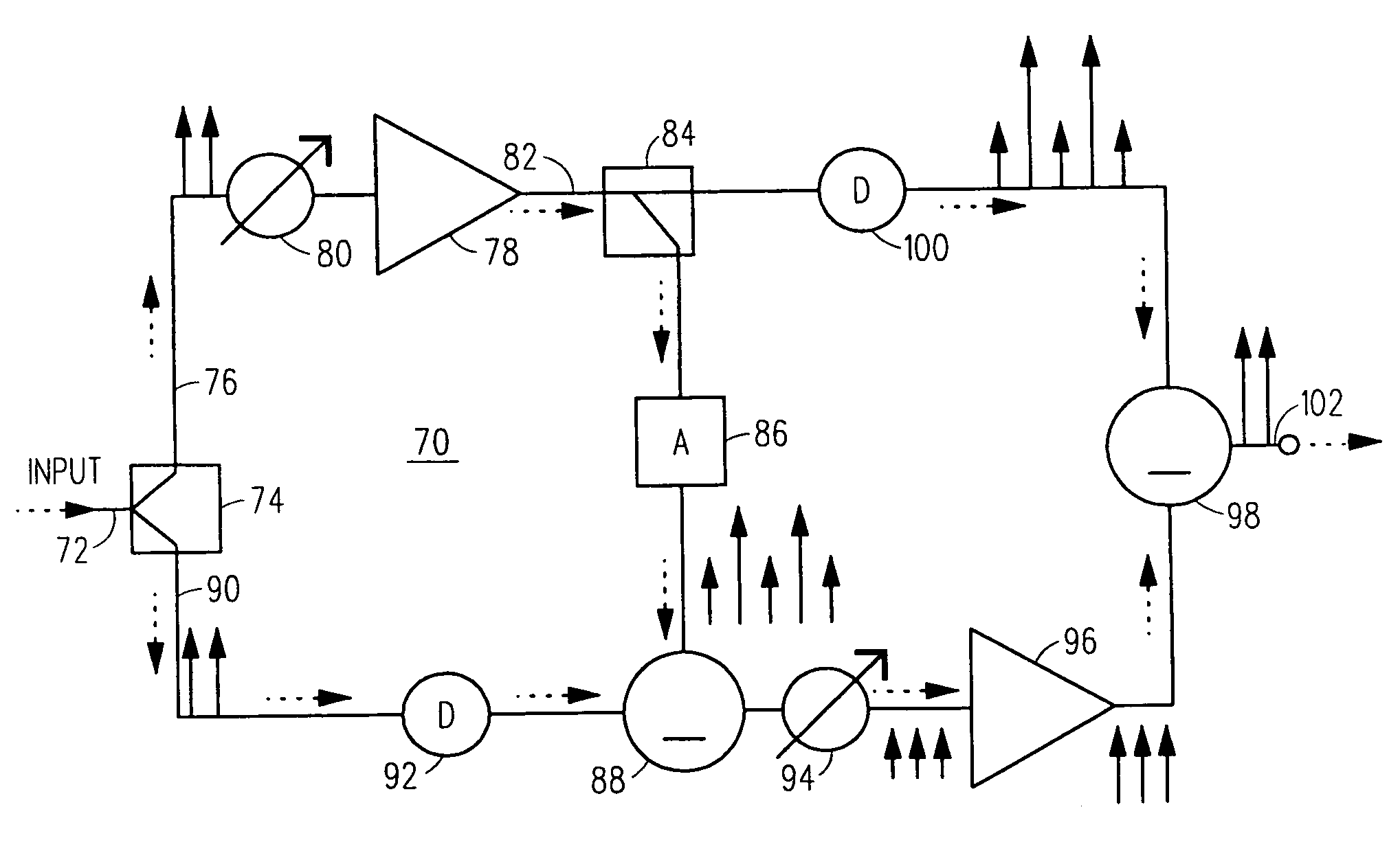
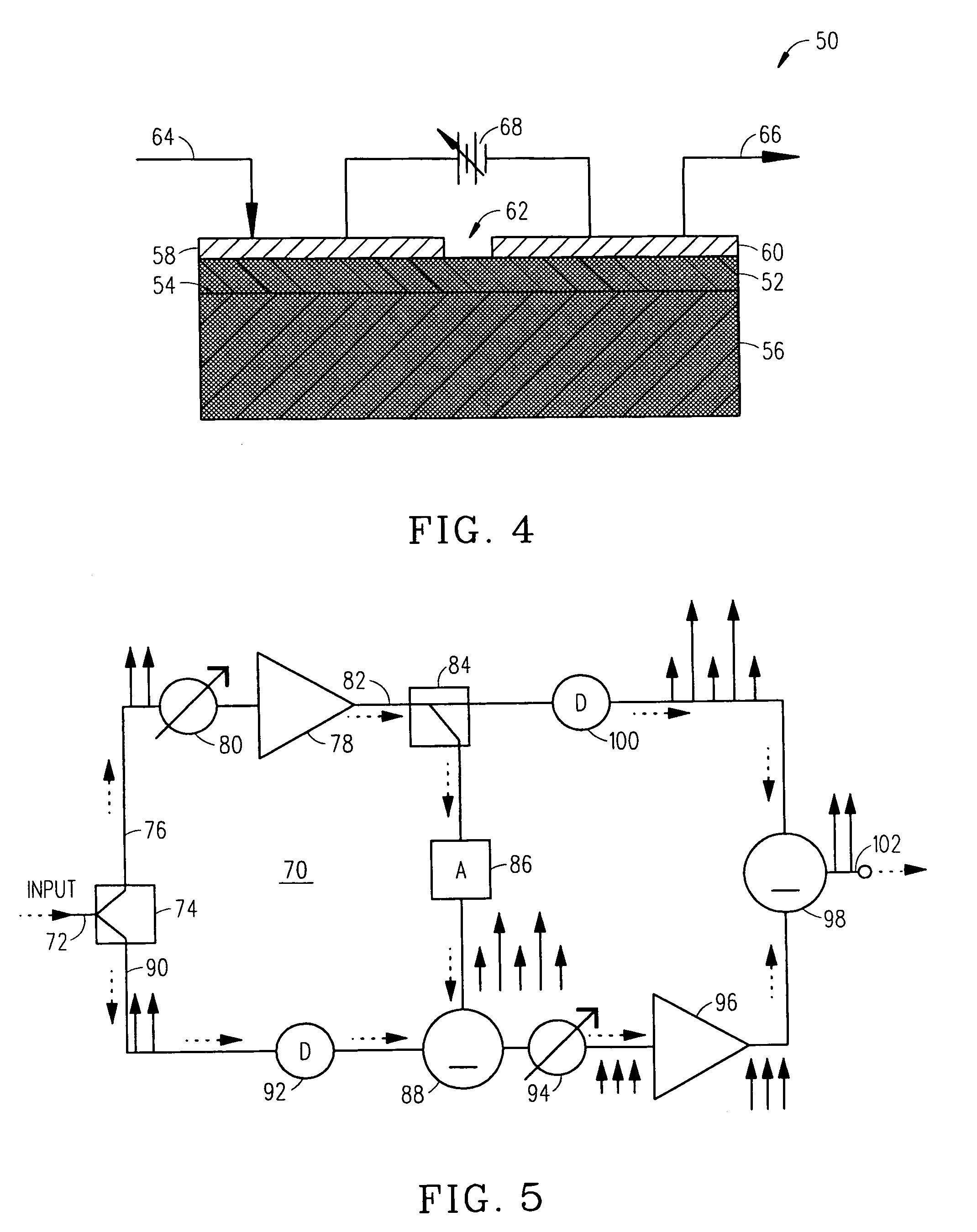
[0070]FIG. 7 is an electrical schematic diagram of an apparatus for reducing influence by selected components in a communication link. In FIG. 7, an apparatus 300 includes a first signal line 302 coupled with a first signal source 304 (exemplified in FIG. 7 as an electromagnetic signal receiving antenna). A second signal line 306 is coupled with a second signal source 308 (exemplified in FIG. 7 as an electromagnetic signal receiving antenna). A signal treating unit 310 is coupled with second signal line 306. Signal treating unit 310 may include, by way of example and not by way of limitation, in a tunable delay line 309, a tunable phase shifting unit (not shown in FIG. 7) or a combination of a tunable delay line 309 and a tunable phase shifting unit. Signal treating unit 310 may also include a signal amplitude adjusting unit 311, such as a signal amplifier, a signal attenuator or a combination of an amplifier and an attenuator.

[0071]A signal combining unit or coupling unit 312 recei...

second embodiment

[0073]FIG. 8 is an electrical schematic diagram of an apparatus for reducing influence by selected components in a communication link. In FIG. 8, an apparatus 400 includes a first signal line 402 coupled with a first signal source 404 (exemplified in FIG. 8 as an electromagnetic signal receiving antenna). A second signal line 406 is coupled with first signal line 402. A signal treating unit 410 is coupled with second signal line 406. Signal treating unit 410 may be embodied, by way of example and not by way of limitation, in a tunable delay line 409, in a tunable phase shifting unit (not shown in FIG. 8) or in a combination of a tunable delay line 409 and a tunable phase shifting unit. Signal treating unit 410 may also include a signal amplitude adjusting unit 411, such as a signal amplifier, or a signal attenuator, or a combination of an amplifier and an attenuator.

[0074]A signal combining unit or coupling unit 412 receives a first communication signal via first signal line 402 fro...


PUM


Abstract

An apparatus for reducing influence by selected signal components in a communication link includes a first signal line conveying a first communication signal including a desired signal component and at least one undesired signal component; a second signal line conveying a second communication signal substantially including at least the at least one undesired signal component; a signal treating unit coupled with the second signal line for affecting at least one parameter associated with the second communication signal to present a modified second communication signal at a first output locus coupled for combining the modified second communication signal with the first communication signal to present an improved communication signal at a second output locus. The at least one undesired signal component affects the improved communication signal less than the at least one undesired signal component affects the first communication signal.

Description

[0001]This application is a Continuation-in-Part of U.S. application Ser. No. 10 / 252,139; filed Sep. 20, 2002 now U.S. Pat. No. 6,801,102, which claims benefit of Provisional Patent Application Ser. No. 60 / 323,729, filed Sep. 20, 2001.FIELD OF INVENTION[0002]This invention relates to electronic filters, and more particularly, to variable bandwidth bandpass filters.BACKGROUND OF INVENTION[0003]Electrically tunable filters have many uses in microwave and radio frequency systems. Compared to mechanically and magnetically tunable filters, electronically tunable filters have the important advantage of fast tuning capability over wide band application. Because of this advantage, they can be used in the applications such as, by way of example and not by way of limitation, LMDS (local multipoint distribution service), PCS (personal communication system), frequency hopping, satellite communication, and radar systems.[0004]Filters for use in radio link communications systems have been require...

Claims


Application Information

Patent Timeline
Patent Type & Authority Patents(United States)
IPC IPC(8): H03H7/12H03H7/20H01P1/203H03F1/32
CPCH01P1/20363H03H7/1775H03H7/12H03F1/3229
Inventor SHAMSAIFAR, KHOSROZHU, YONGFEIKVARNSTRAND, JOHNSENGUPTA, LOUISE
Owner NXP USA INC
Learn More