
Surface mount antenna, and an antenna element mounting method

a surface mount antenna and antenna element technology, applied in the direction of resonant antennas, antenna earthings, elongated active element feeds, etc., can solve the problems that the antenna element itself cannot be standardized without drastic improvements, and the problem of solving the problem

Inactive Publication Date: 2006-04-25
SONY CORP
View PDF10 Cites 58 Cited by
  • Summary
  • Abstract
  • Description
  • Claims
  • Application Information

AI Technical Summary

Benefits of technology

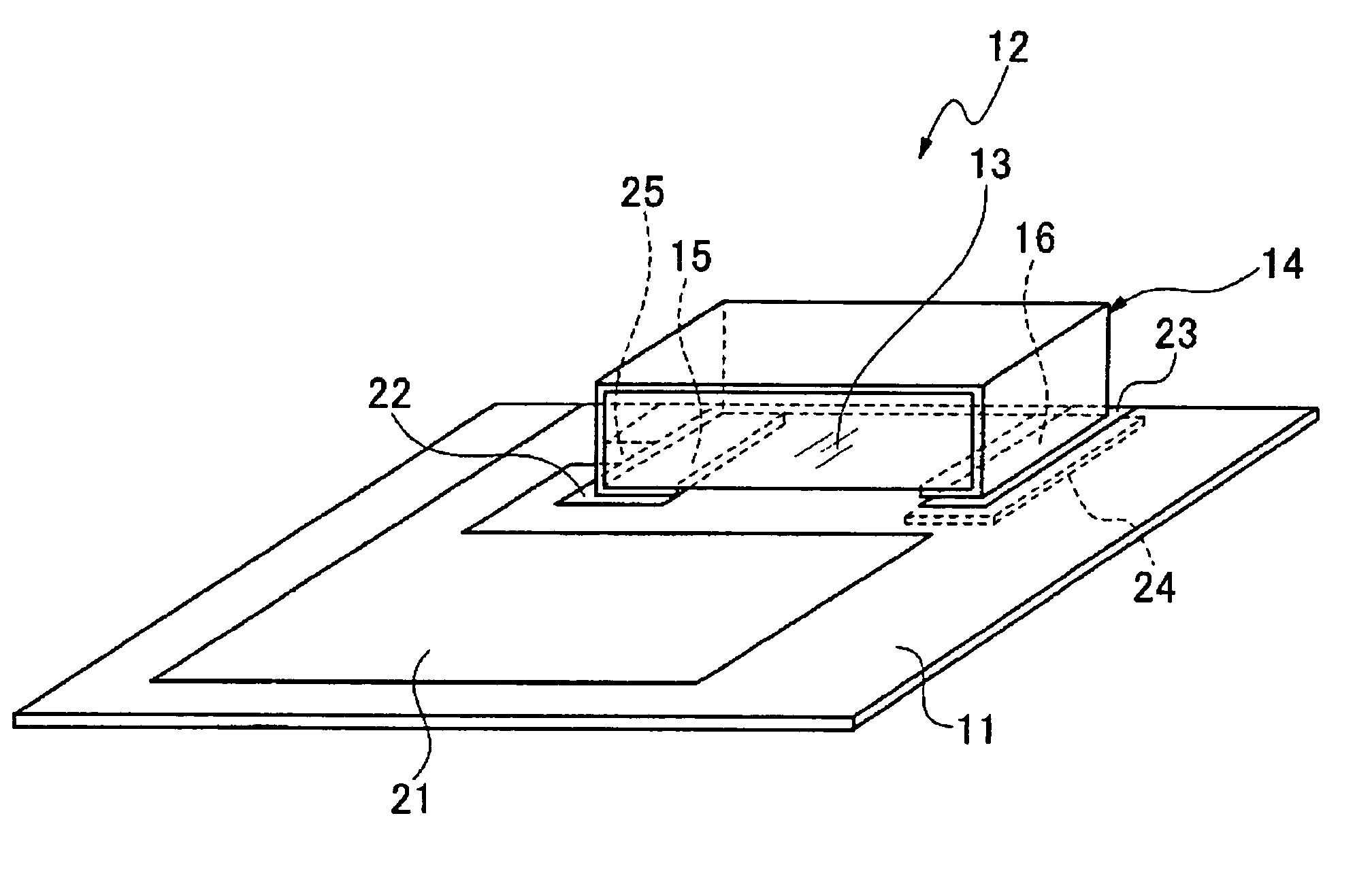
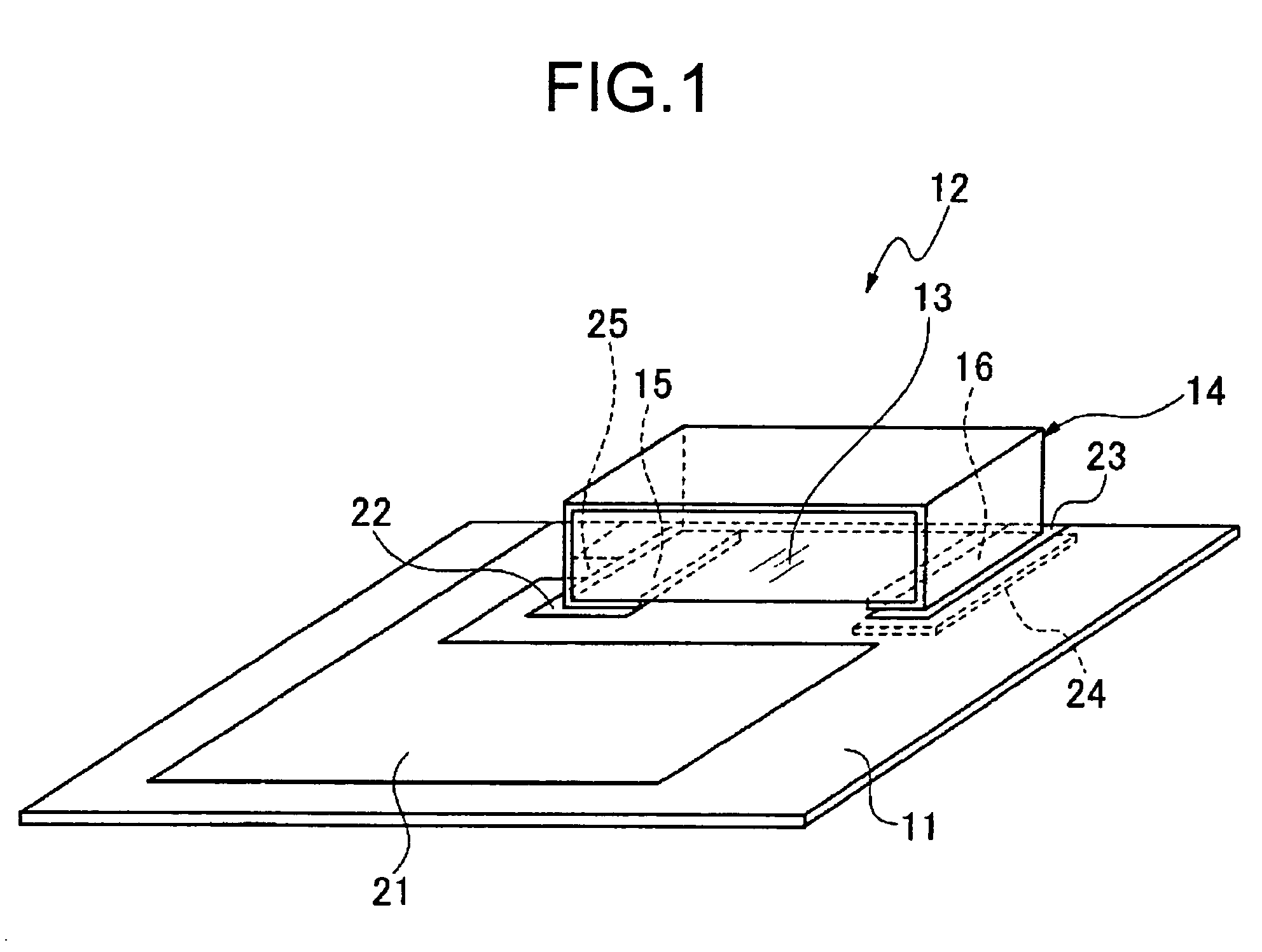
[0010]According to the present invention as described above, a utilized frequency is adjusted by changing an impedance by varying a pattern width of a portion connecting a ground electrode of the above mentioned electrodes and a GND pattern of a ground side of the board, and an impedance matching is performed by changing a capacitance based on a dielectric constant of the board by varying area of a surface of a feed pattern at a position of a feed side of the board in opposing relation to a feed electrode of the above mentioned electrodes while the shapes of the dielectric material and the electrodes configuring the antenna element are left unchanged. Therefore, it becomes possible to adjust a predetermined utilized frequency and to perform an impedance matching by changing the GND pattern side and the feed pattern side without changing the shape of the antenna element. This means that it is possible to standardize the antenna element by using the common antenna element, even though the board side of the set may have a change or an external factor.

Problems solved by technology

Accordingly, in standardizing the mount parts, there is a problem that the antenna element itself is not able to be standardized without drastic improvements.
Accordingly, in an antenna element mounting method and a surface mount antenna realizing the use of a standard antenna element even in the different set, there is a problem to be solved.

Method used


Image

  • Surface mount antenna, and an antenna element mounting method
  • Surface mount antenna, and an antenna element mounting method
  • Surface mount antenna, and an antenna element mounting method

Examples


Embodiment Construction

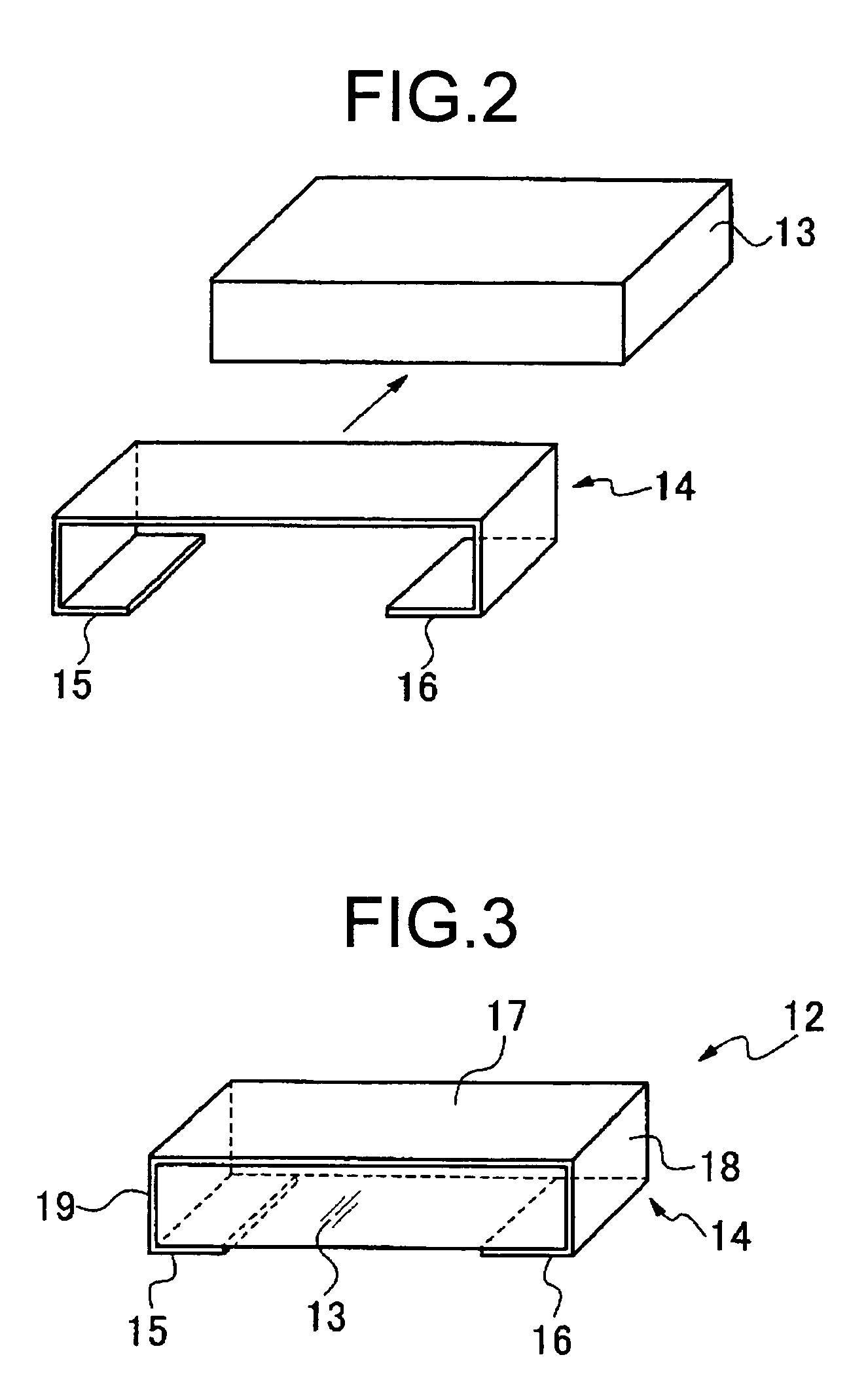
[0021]Now, embodiments of a surface mount antenna and an antenna element mounting method according to the present invention are described with reference to the accompanying drawings. In a surface mount antenna capable of specifying the antenna element mounting method of the present invention, an antenna element 12 is mounted on a part of a surface of a board 11 as shown in FIG. 1, and this surface mount antenna's utilized frequency is adjusted by adjusting a pattern width of a ground pattern 25 connected to a GND pattern 21 which is connected to a ground electrode 15 of the antenna element 12, and an impedance matching is carried out by adjusting a positional relation of a feed pattern located in opposed relation to a feed mount pattern 23 of the feed side connected to a feed electrode 16.

[0022]The antenna element 12 is formed as to cover surfaces of a dielectric material 13 formed with a rectangular solid shaped ceramics or the like by a metal electrode 14 as shown in FIG. 2 and FI...


PUM


Abstract

A surface mount antenna is configured by mounting on a board a dielectric material on which electrodes are provided, wherein an antenna element comprises the electrodes having a ground electrode and a feed electrode, and a ground mount pattern connected to the ground electrode of the electrode and a feed mount pattern connected to the feed electrode of the electrode are formed on the board with a predetermined distance in-between. A frequency is adjusted by changing impedance by varying a pattern width of a portion connecting a ground electrode of the electrodes and a GND pattern of a ground side of the board, and an impedance matching is performed by changing capacitance based on dielectric constant of the board by varying area of a surface of a feed pattern at a position where a feed electrode of the electrodes and a feed side of the board are in opposing relation.

Description

CROSS REFERENCE TO RELATED APPLICATION[0001]This application claims priority from Japanese Priority Document No. 2003-152443, filed on May 29, 2003 with the Japanese Patent Office, which document is hereby incorporated by reference.BACKGROUND OF THE INVENTION[0002]1. Field of the Invention[0003]This invention relates to an antenna element mounting method and a surface mount antenna, and more particularly to a surface mount antenna designed to standardize an antenna element to be mounted on a set, and an antenna element mounting method.[0004]2. Description of the Related Art[0005]A surface mount antenna of a conventional technology is such that an antenna has an antenna element formed with electrodes on surfaces of dielectric material or magnetic material. The antenna of this type is designed to perform an impedance matching at a feed section by itself, and to match with a predetermined utilized frequency. For example, see Japanese Laid-Open Patent No. PH10-173434.[0006]However, in t...

Claims


Application Information

Patent Timeline
Patent Type & Authority Patents(United States)
IPC IPC(8): H01Q1/38H01Q13/08H01Q1/12H01Q1/24H01Q9/04H01Q9/40
CPCH01Q9/0421H01Q1/38
Inventor SEKIGUCHI, MASAMIKANEKO, MASAYASU
Owner SONY CORP
Learn More