
Compact multiple-band antenna arrangement

a multi-band antenna and antenna arrangement technology, applied in the field of antenna elements, can solve the problems of asymmetric beam pattern of antennas, low cost of least some of these antennas,

Inactive Publication Date: 2006-04-25
ALCATEL-LUCENT USA INC
View PDF11 Cites 27 Cited by
  • Summary
  • Abstract
  • Description
  • Claims
  • Application Information

AI Technical Summary

Benefits of technology

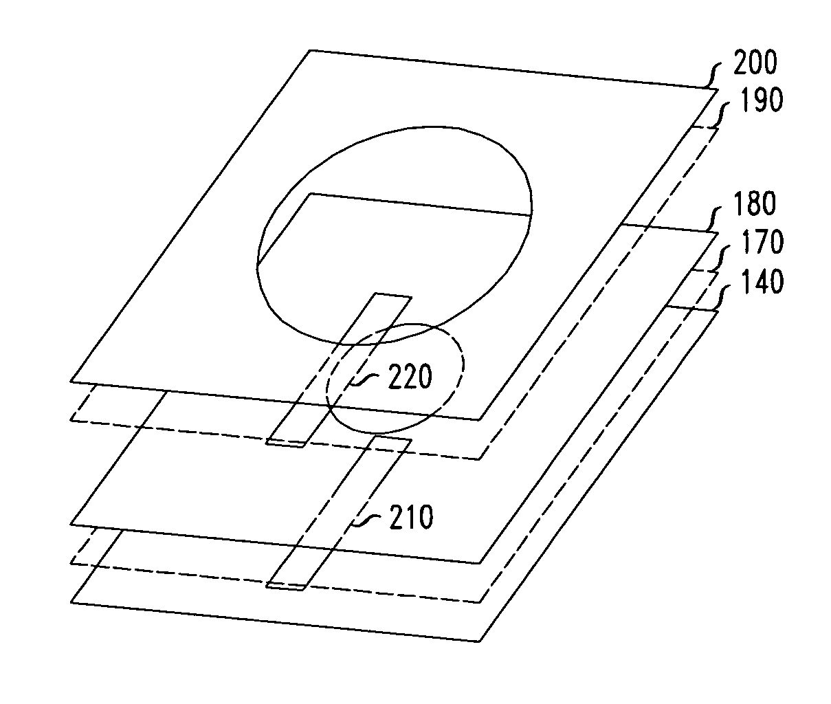
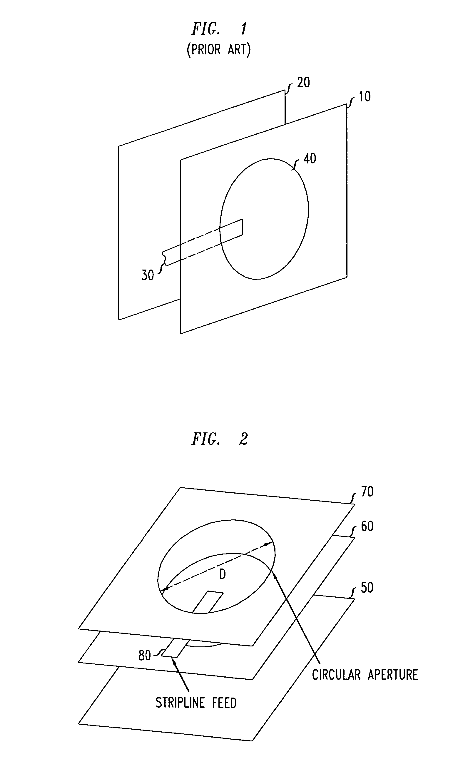
"The present invention provides a single antenna element that can work in multiple frequency bands, has symmetrical beam patterns, and is easy and cheap to make. The antenna has at least three conductive plates arranged in a stack, with at least one pair of adjacent plates containing mutually aligned apertures. It also includes at least one air stripline that creates electromagnetic excitation of the apertures when energized. In some embodiments, one end of the stack is not apertured, which adds directionality to the beam pattern. In other embodiments, at least two apertures are differently sized, which allows for resonant operation in at least two frequency bands."

Problems solved by technology

However, at least some of these antennas are relatively expensive because they have relatively many components which furthermore comprise several different construction materials.
Such construction from multiple elements is generally disadvantageous because it leads to overall antennas that are ungainly and visually obstructive, and because it may also lead to antennas having asymmetric beam patterns.

Method used


Image

  • Compact multiple-band antenna arrangement
  • Compact multiple-band antenna arrangement
  • Compact multiple-band antenna arrangement

Examples


example

[0057]As noted above, we constructed prototype antenna elements of the kinds depicted in FIGS. 2 and 4. The plates were stamped from 150-mm-square brass sheets 0.5 mm in thickness.

[0058]In the element of FIG. 2, the aperture diameters were both 90 mm. The lower apertured plates was spaced 38 mm from the reflector plate, as measured from the center of the aperture.

[0059]In the element of FIG. 4, the aperture diameters and the positions of the apertured plates relative to the reflector plate were optimized for performance in the designated frequency bands.

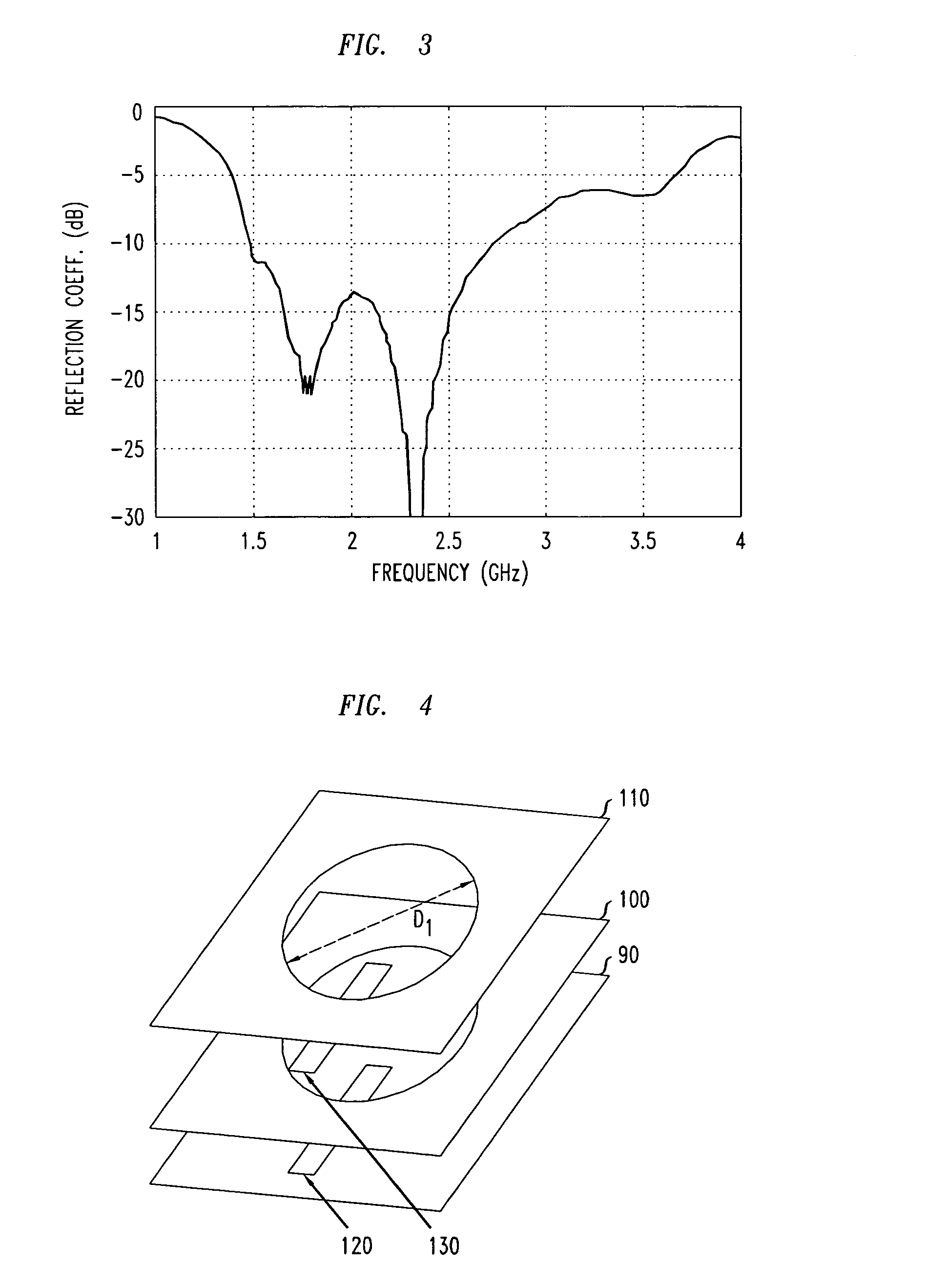
[0060]As noted above, we measured the frequency dependence of the feed-signal reflection coefficient for the single feed of the antenna element of FIG. 2, and for the two feeds of the antenna element of FIG. 4. The results are plotted in FIGS. 3 and 5, respectively, and are discussed above.

[0061]We also measured antenna characteristics (i.e., sensitivity or radiation patterns) for our prototype of the antenna element of FIG. 2 at two...


PUM


Abstract

An antenna element is provided which responsive in multiple frequency bands, has symmetric beam patterns, and is easily and cheaply fabricated. The antenna element includes at least three conductive plates arranged in a stack At least one pair of adjacent plates contain apertures that are mutually aligned relative to the stacking direction. The antenna element further includes at least one air stripline arranged to create radiative electromagnetic excitations of the apertures when the stripline or striplines are energized by a suitable radiofrequency voltage source or sources.

Description

FIELD OF THE INVENTION[0001]This invention relates to antenna designs for wireless communication, and more particularly to the design of antenna elements that can be used in more than one frequency band.ART BACKGROUND[0002]As wireless communication technology continues to develop, it is inevitable that emerging wireless services will coexist with established services for at least some period of time. For example, some parts of the world already see, or will soon see, UMTS service coexisting with GSM. One way for wireless service providers to save money, at least in such interim periods, is to install base station equipment that is suitable for use in multiple frequency bands, which include the bands of both the established and the emerging services. In particular, it will be useful to install antennas suitable for use in more than one frequency band.[0003]Multiple-band antennas are known. However, at least some of these antennas are relatively expensive because they have relatively ...

Claims


Application Information

Patent Timeline
Patent Type & Authority Patents(United States)
IPC IPC(8): H01Q13/10H01Q13/12H01Q5/00H01Q5/42H01Q21/00H01Q21/06H01Q21/28
CPCH01Q21/0081H01Q5/42H01Q21/28H01Q21/064H01Q13/10
Inventor FISCHER, GEORGPIVIT, FLORIAN
Owner ALCATEL-LUCENT USA INC
Learn More