
Method of assaying downhole occurrences and conditions

a technology of occurrence and conditions, applied in the field of oil and gas well drilling industry, can solve the problems of not being able to see downhole, all less than ideal,

Inactive Publication Date: 2006-04-25
HALLIBURTON ENERGY SERVICES INC
View PDF122 Cites 48 Cited by
  • Summary
  • Abstract
  • Description
  • Claims
  • Application Information

AI Technical Summary

Benefits of technology

[0014]According to another embodiment of the present invention, work of the bit can be determined using bit mechanical efficiency, where the mechanical efficiency of the bit is based upon a percentage of a total torque applied by the bit which is cutting torque. As a result, effects of the operating torque of a drilling rig or apparatus, being used or considered for use in

Problems solved by technology

From the very beginning of the oil and gas well drilling industry, as we know it, one of the biggest challenges has been the fact that it is impossible to actually see what is going on downhole.
To that extent, they are all less than ideal, and there is a constant effort in the industry to develop simpler and / or more accurate methods.

Method used


Image

  • Method of assaying downhole occurrences and conditions
  • Method of assaying downhole occurrences and conditions
  • Method of assaying downhole occurrences and conditions

Examples


Embodiment Construction

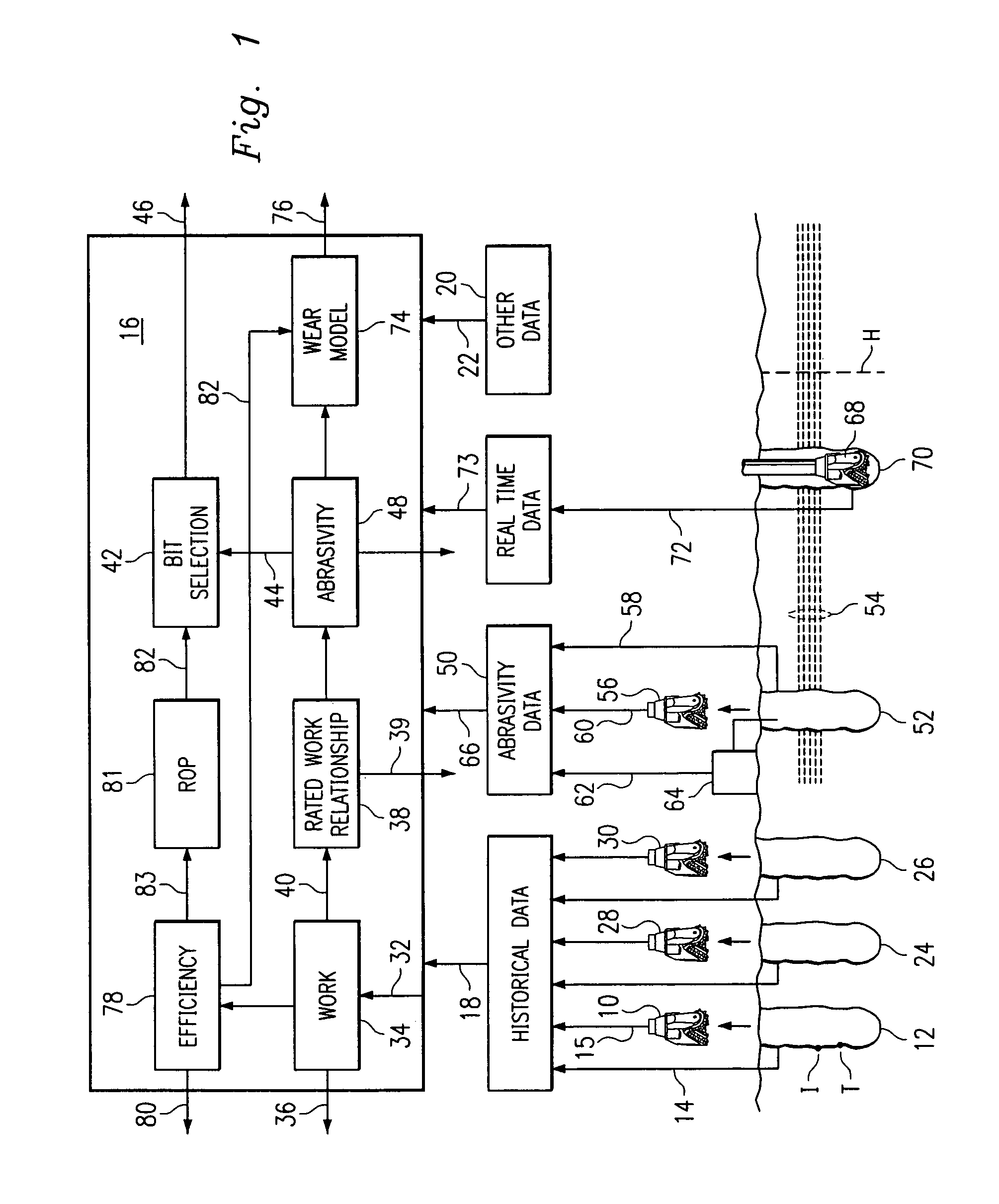
[0029]Referring to FIG. 1, the most basic aspect of the present invention involves assaying work of a well drilling bit 10 of a given size and design. A well bore or hole 12 is drilled, at least partially with the bit 10. More specifically, bit 10 will have drilled the hole 12 between an initial point I and a terminal point T. In this illustrative embodiment, the initial point I is the point at which the bit 10 was first put to work in the hole 12, and the terminal point T is the point at which the bit 10 was withdrawn. However, for purposes of assaying work per se, points I and T can be any two points which can be identified, between which the bit 10 has drilled, and between which the necessary data, to be described below, can be generated.

[0030]The basic rationale is to assay the work by using the well known relationship:

Ωb=FbD  (1)[0031]where:[0032]Ωb=bit work[0033]Fb=total force at the bit[0034]D=distance drilled

[0035]The length of the interval of the hole 12 between points I an...


PUM


Abstract

A method of assaying work of an earth boring bit of a given size and design including establishing characteristics of the bit of given size and design. The method further includes simulating a drilling of a hole in a given formation as a function of the characteristics of the bit of given size and design and at least one rock strength of the formation. The method further includes outputting a performance characteristic of the bit, the performance characteristic including a bit wear condition and a bit mechanical efficiency determined as a function of the simulated drilling.

Description

CROSS REFERENCE[0001]This is a continuation of U.S. Ser. No. 09 / 434,322, filed Nov. 4, 1999 abandoned, which is a divisional of U.S. Ser. No. 09 / 048,360 filed Mar. 26, 1998 U.S. Pat. No. 6,131,673, which is a continuation-in-part of Ser. No. 08 / 621,411 filed on Mar. 25, 1996 U.S. Pat. No. 5,794,720.BACKGROUND OF THE INVENTION[0002]From the very beginning of the oil and gas well drilling industry, as we know it, one of the biggest challenges has been the fact that it is impossible to actually see what is going on downhole. There are any number of downhole conditions and / or occurrences which can be of great importance in determining how to proceed with the operation. It goes without saying that all methods for attempting to assay such downhole conditions and / or occurrences are indirect. To that extent, they are all less than ideal, and there is a constant effort in the industry to develop simpler and / or more accurate methods.[0003]In general, the approach of the art has been to focus ...

Claims


Application Information

Patent Timeline
IPC IPC(8): G06F17/50E21B47/00E21B12/02E21B41/00E21B44/00E21B49/00
CPCE21B12/02E21B44/00E21B49/003E21B44/005E21B2041/0028E21B2200/22
Inventor GOLDMAN, WILLIAM A.SMITH, LEE MORGAN
Owner HALLIBURTON ENERGY SERVICES INC
Learn More