Apparatus and method for handling of tubulars

Inactive Publication Date: 2006-05-02
WEATHERFORD TECH HLDG LLC
View PDF23 Cites 53 Cited by
  • Summary
  • Abstract
  • Description
  • Claims
  • Application Information

AI Technical Summary

Benefits of technology

[0004]Although it only takes a relatively short time to mount and remove a stabbing guide it would be

Problems solved by technology

Typically the tubulars are not in perfect align

Method used


Image

  • Apparatus and method for handling of tubulars
  • Apparatus and method for handling of tubulars
  • Apparatus and method for handling of tubulars

Examples


Embodiment Construction

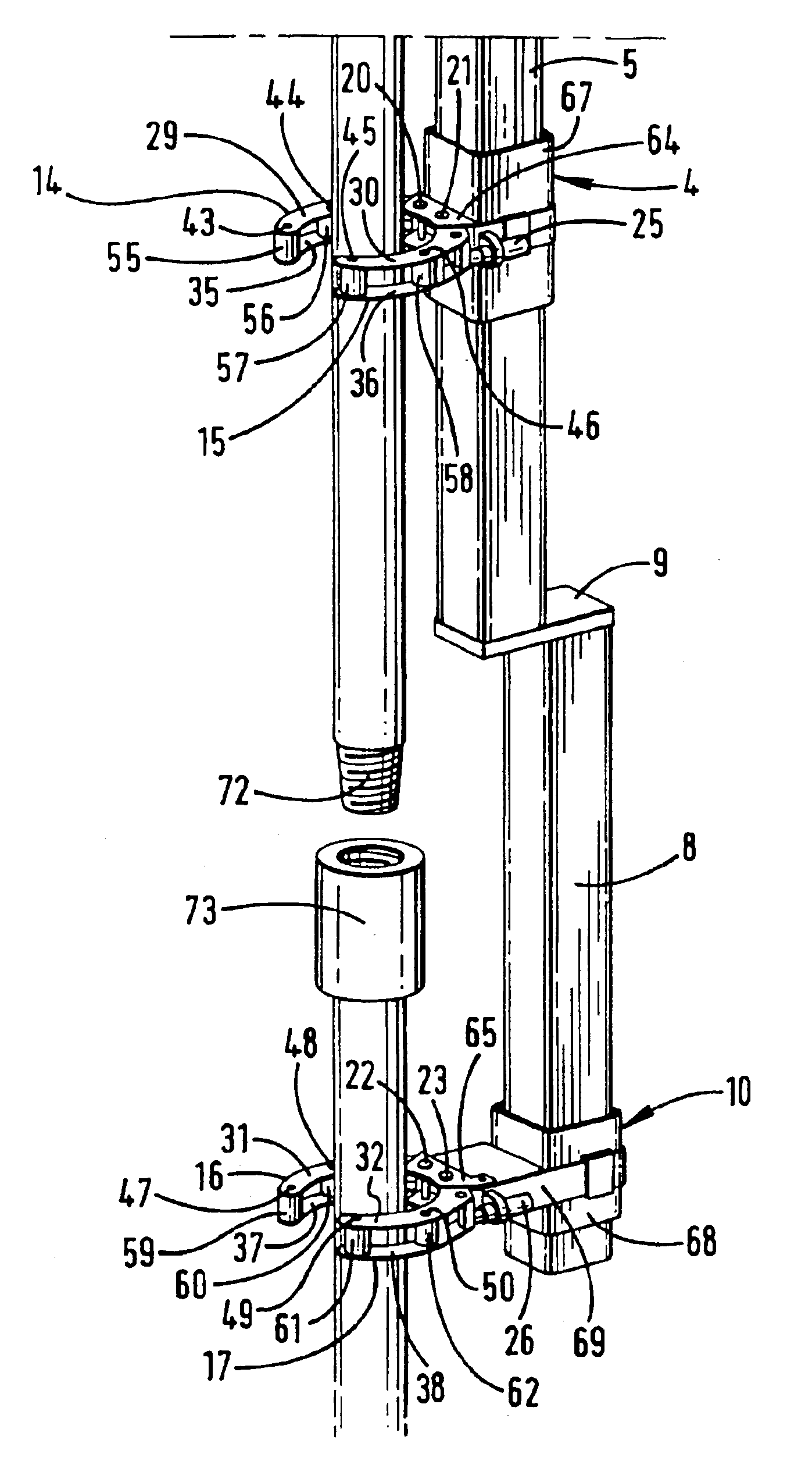
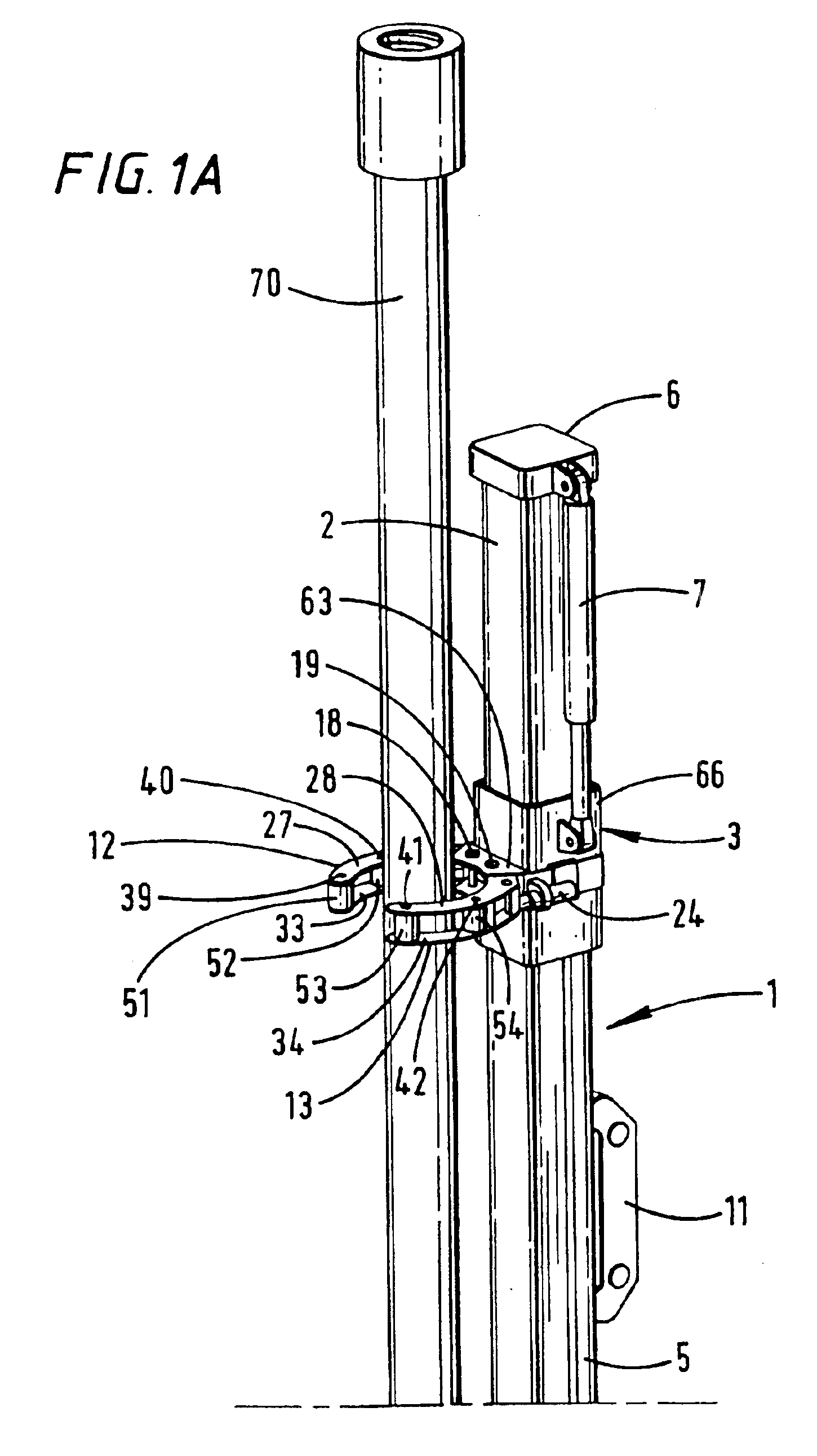
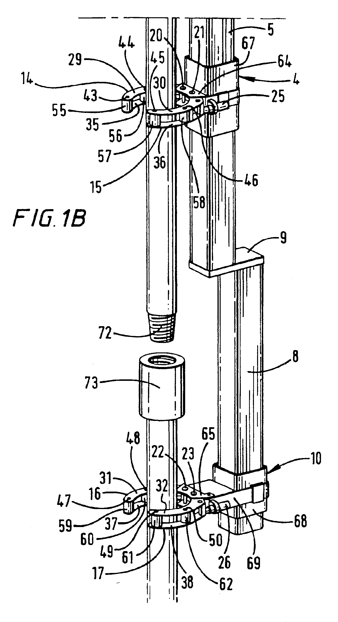
[0026]Referring to the drawings there is shown an apparatus which is generally identified by reference numeral 1.

[0027]The apparatus 1 comprises a substantially vertical box-section upper strut 2 which has longitudinally spaced upper and lower clamping units 3 and 4 slidably mounted thereon. The upper and lower clamping units 3 and 4 are linked by a bar 5. The upper clamping unit 3 is attached to the piston of a hydraulic piston and cylinder 7. Activation of the hydraulic piston and cylinder 7 moves the upper and lower clamping units 3 and 4 along the upper strut 2.

[0028]A substantially vertical box-section lower strut 8 is attached to the upper strut 2 by a plate 9. The lower strut 8 is set back from the upper strut 2. A guide in the form of a clamping unit 10 is arranged near the lower end of the lower strut 8.

[0029]The apparatus 1 is connectable to a standard pipe handling arm (not shown) in place of the known clamping device described hereinbefore via lug 11.

[0030]Each clamping ...


PUM

PropertyMeasurementUnit
Lengthaaaaaaaaaa

Abstract

The present invention provides an apparatus for attachment to pipe handling arm, comprising a clamp for gripping a tubular and a guide for aligning said tubular with another tubular prior to connection thereof, characterized in that said clamp and said guide are movable relative to each other in a direction longitudinal of the tubular, the arrangement being such that said tubular can be brought closer to said another tubular in a direction longitudinal of the tubular.

Description

CROSS-REFERENCE TO RELATED APPLICATIONS[0001]This application is a continuation of U.S. patent application Ser. No. 09 / 600,764, filed Sep. 19, 2000 U.S. Pat. No. 6,550,128 which is a 371 of PCT / GB99 / 00432 filed Feb. 11, 1999. The aforementioned related patent application is herein incorporated by reference.BACKGROUND OF THE INVENTIONField of the Invention[0002]Embodiments of the present invention generally relate to an apparatus or attachment to a pipe handling arm and to a method of handling a tubular.SUMMARY OF THE INVENTION[0003]Pipe handling apparatus generally comprises a pipe handling arm and a clamp. The pipe handling arm is fixed at one end to a derrick or to a rig floor of a drilling rig. The other end of the pipe handling arm is free to move in at least one plane, and usually two or three planes. The clamp is attached to the free end of the pipe handling arm In use, the free end of the pipe handling arm is swung over to a pipe rack. The clamp clamps on to a tubular and the...

Claims


Application Information

Patent Timeline
IPC IPC(8): B25B27/00E21B19/18E21B19/15E21B19/20
CPCE21B19/155E21B19/20Y10T29/49998Y10T29/53917Y10T29/49895Y10T29/53961
Inventor LORENZ, GEORG
Owner WEATHERFORD TECH HLDG LLC
Why Eureka
Try Eureka