Afterglow lamp with multiple phosphor coatings

Inactive Publication Date: 2002-11-12
MARTINEZ JORGE MATARRODONA
View PDF8 Cites 27 Cited by
  • Summary
  • Abstract
  • Description
  • Claims
  • Application Information

AI Technical Summary

Benefits of technology

Another drawback of the current technique is the high cost of the so-called emergency lamps

Problems solved by technology

The problem that arises when there is a power cut in a lighting installation, whether on business premises and within dwelling units, or outdoors, is well-known.
However, this solution provides isolated light spots which fail to define paths for people to find their way, which hampers th

Method used


Image

  • Afterglow lamp with multiple phosphor coatings
  • Afterglow lamp with multiple phosphor coatings

Examples


Example

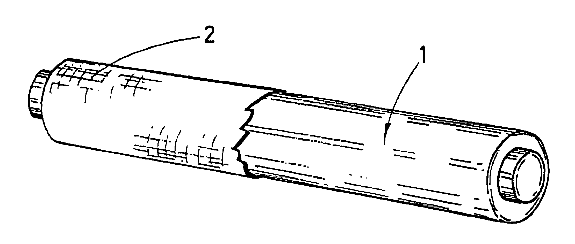
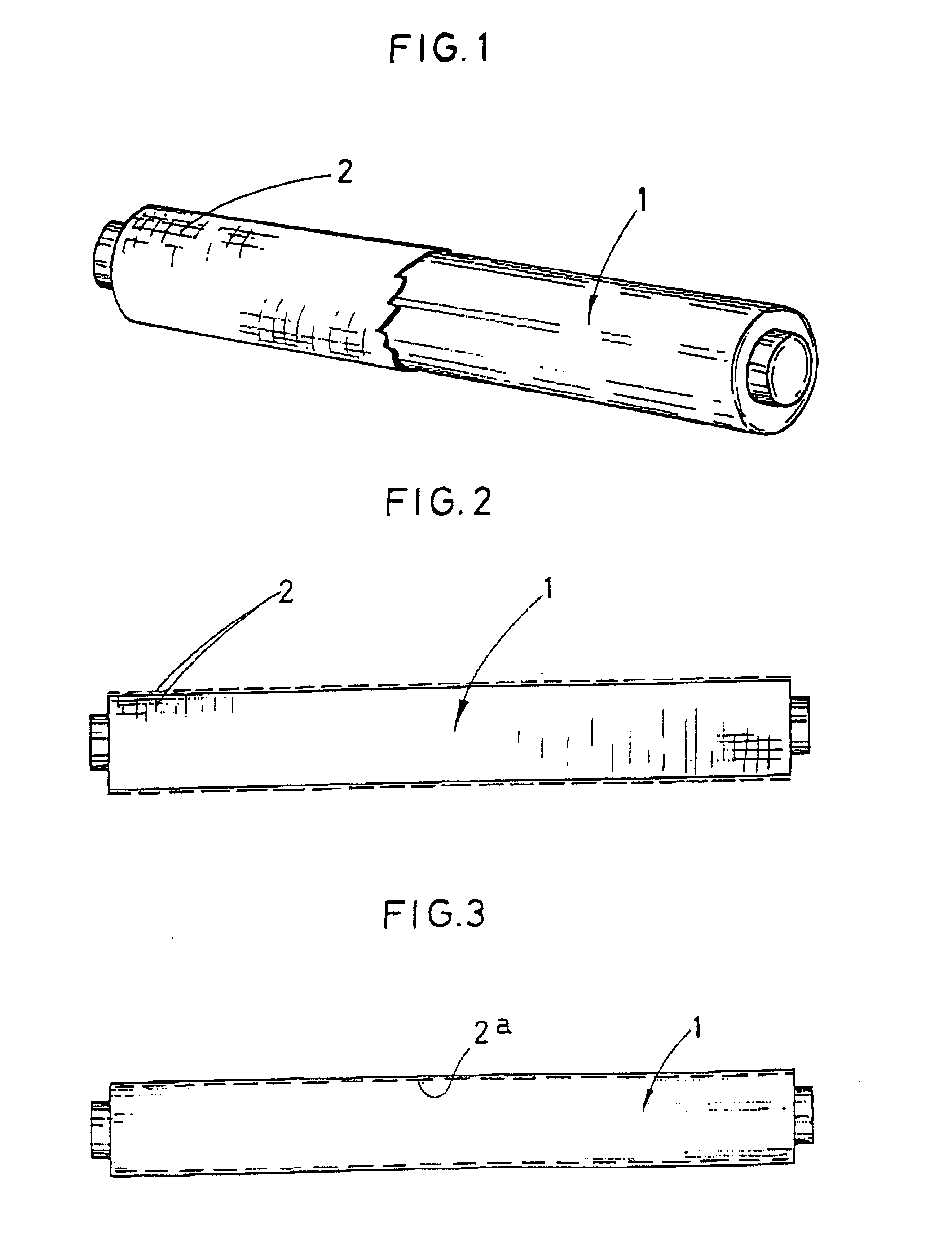
The applicant filing the present patent application has devised an improved lamp, based on a generic type lamp, preferably a fluorescent tubular lamp, using the tube as the element supporting a luminescent type product, preferably strontium aluminate SrAl.sub.2 O.sub.4 :EuDy and others, capable of capturing light coming from a source and emitting it when the source of excitation stops working.

It follows from the foregoing that upon treating the surface of a lamp, whether it be the glass bulb of an incandescent lamp or the glass tube of a fluorescent lamp, a luminescent spot or line will result which, a long with all the other lamps on the business premises, shall provide broken lines defining paths to be followed by people in the event of a power cut, lasting for between five and sixty minutes, say thirty minutes for instance.

The advantages over the currently known technique, summarily described in the preceding section, are self-evident, not only because of its effectiveness, but m...


PUM


Abstract

Improved lamp of the type comprising the crystal bulb of an incandescent lamp or the crystal tube of a fluorescent lamp or preferably of the type comprised of a tube-shaped fluorescent lamp, characterized in that the structure of the tube itself forms a support for a luminescent product arranged as a coating which captures the light proceeding from a source and generated by the lamp itself thereby enabling it to emit its own light after the excitation has stopped thereby providing a self-contained lighting element.

Description

OBJECT OF THE INVENTIONThe object of the present patent application is an improved lamp which, in addition to the function for which it was designed, contributes a number of advantages that shall be set out hereinafter, besides others inherent in the arrangement and construction thereofThe problem that arises when there is a power cut in a lighting installation, whether on business premises and within dwelling units, or outdoors, is well-known.The current approach to solve this problem involves installing battery-powered emergency lamps. However, this solution provides isolated light spots which fail to define paths for people to find their way, which hampers their movement, particularly when in major stores or on business premises which have complex subdivisions.Another drawback of the current technique is the high cost of the so-called emergency lamps, specifically devised for such purpose, and their accessories, rechargeable batteries, etc.DESCRIPTION OF THE INVENTIONThe applican...

Claims


Application Information

Patent Timeline
IPC IPC(8): C09K11/77H01J61/38H01J61/48F21V9/16F21V9/00C09K11/08F21K2/00H01J61/44
CPCC09K11/7739C09K11/7792H01J61/48F21V9/16H01J61/44H01J61/35F21V9/32H01J1/35
Inventor MARTINEZ, JORGE MATARRODONA
Owner MARTINEZ JORGE MATARRODONA
Why Eureka
Try Eureka