Method and device for configuring reference signal information

A technology of reference signal and configuration method, applied in the field of communication, can solve the problems of large overhead of DMRS port configuration information and the like

Active Publication Date: 2018-06-01
ZTE CORP
View PDF8 Cites 26 Cited by
  • Summary
  • Abstract
  • Description
  • Claims
  • Application Information

AI Technical Summary

Problems solved by technology

[0009] Embodiments of the present invention provide a method and device for configuring reference signal information to at least solve the problem of high overhead in notifying DMRS port configuration information in the related art

Method used


Image

  • Method and device for configuring reference signal information
  • Method and device for configuring reference signal information
  • Method and device for configuring reference signal information

Examples


Embodiment 1

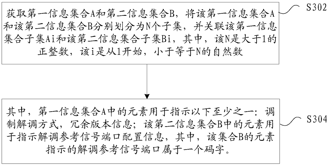
[0054] In this embodiment, a configuration of reference signal information running on the above network architecture is provided, image 3 is a flowchart of a method for configuring reference signal information according to an embodiment of the present invention, as shown in image 3 As shown, the process includes the following steps:

[0055] Step S302, obtaining the first information set A and the second information set B, dividing the first information set A and the second information set B into N subsets respectively, and associating the first information set subset Ai with the second information set Two information set subsets Bi, wherein, the N is a positive integer greater than 1, and the i is a natural number starting from 1 and less than or equal to N;

[0056] Step S304, wherein, the elements in the first information set A are used to indicate at least one of the following: modulation and demodulation mode, redundancy version information; the elements in the second ...

Embodiment 1

[0097] Preferred embodiment 1: the scheme of DMRS type 2

[0098] For the current design of reference signals, a DMRS pattern based on FD-OCC (Frequency domain orthogonal covering code), we call it DMRS type 2, which can effectively support a maximum of 6 ports in one DMRS symbol (such as Figure 4 shown), supports a maximum of 12 ports in 2 DMRS symbols (such as Figure 5 shown).

[0099] Figure 4 It is a schematic diagram of DMRS type 2 in the preferred embodiment 1 of the present invention Figure 1 ,Such as Figure 4 As shown, in one RB (Resource block), the abscissa is the time domain, and the ordinate is the frequency domain. The 6 DMRS ports are divided into 3 DMRS port groups, and port group #0 includes ports p0 and p1. In port group #0, ports p0 and p1 are mapped to the same time-frequency resource by means of OCC codes. For example, the OCC code used by port p0 is [1 1], and the OCC code used by port p1 is [1 -1]. In one RB, subcarriers mapped to ports p0 and ...

Embodiment 1a

[0117] Preferred Embodiment 1a: Scheme of DMRS Type 1

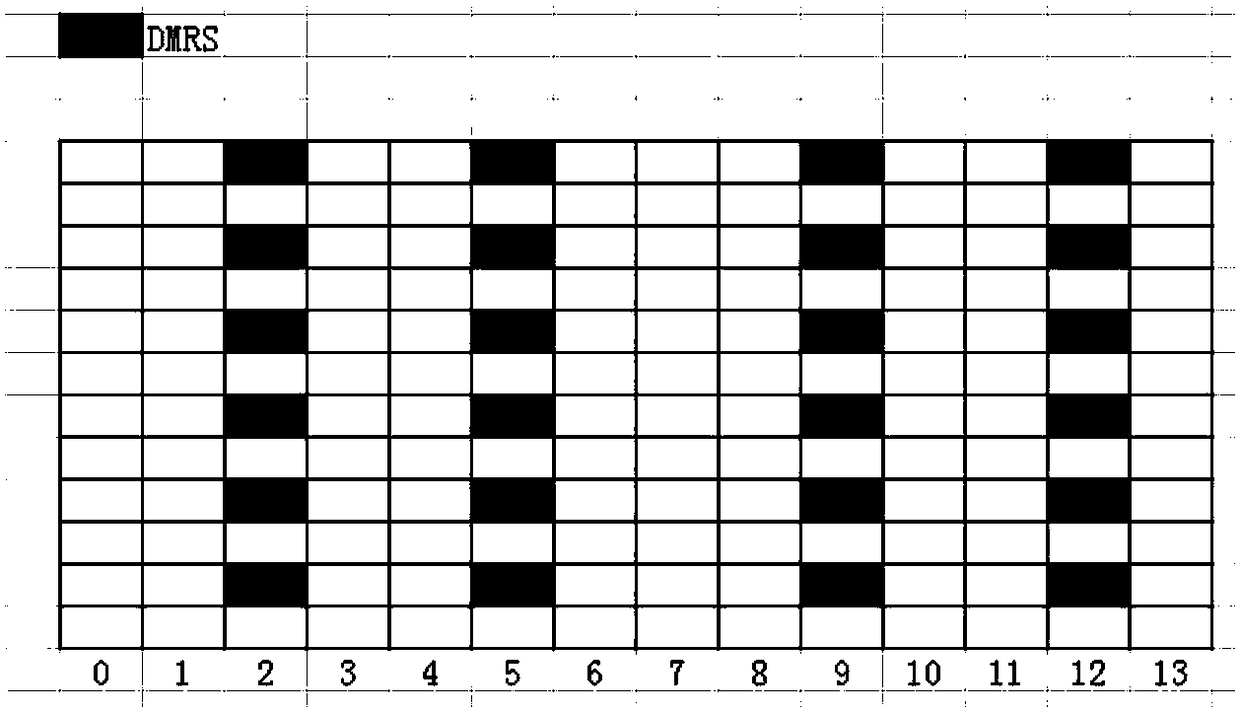
[0118] A DMRS pattern based on IFDM (Interleaved Frequency domain multiplexing), which we call DMRS type 1, can effectively support a maximum of 4 ports in one DMRS symbol (such as Image 6 shown), supports a maximum of 8 ports in 2 DMRS symbols (such as Figure 7 shown).

[0119] Image 6 It is a schematic representation of DMRS type 1 in preferred embodiment 1 of the present invention Figure 1 ,exist Image 6 In the above, the DMRS port is divided into two port groups, port group #0 includes p0, p2, and p0, p2 occupy the same time-frequency resources, and are distinguished by different codes, for example, by different CS (cyclic shift) sequences . Port group #1 includes p1 and p3, and p1 and p3 occupy the same time-frequency resource and are distinguished by different codes.

[0120] Figure 7 It is a schematic representation of DMRS type 1 in preferred embodiment 1 of the present invention Figure II ,exist ...


PUM


Abstract

The invention provides a method and a device for configuring reference signal information. The method comprises the following steps of acquiring a first information set A and a second information setB, respectively dividing the first information set A and the second information set B into N subsets, and associating a first information set subset Ai and a second information set subset Bi, whereinelements in the first information set A are used for indicating at least one of a modulation-demodulation mode and redundant version information; the elements in the second information set B are usedfor indicating configuration information of a demodulation reference signal port, wherein the demodulation reference signal port indicated by the elements of the set B belongs to a code word. Throughadoption of the technical scheme, the first information set and the second information set are acquired, and the two information sets are associated and sent to a communication node of the opposite end, a problem that the overhead of the configuration information of the DMRS port is large in the correlation technique is solved, and the overhead of the configuration information of the DMRS port isgreatly reduced.

Description

technical field [0001] The present invention relates to the communication field, in particular, to a method and device for configuring reference signal information. Background technique [0002] In related technologies, if the demodulation reference signal is configured to transmit corresponding data on the time domain symbol where the demodulation reference signal is located, then the power of the demodulation reference signal cannot be enhanced, and a large amount of additional signaling is required to indicate the data Whether data was sent on the same time-domain symbol as the demodulation reference signal. However, if the data is not configured to be sent on the time-domain symbol where the demodulation reference signal is located, the signaling overhead is reduced, but the transmission efficiency may be reduced. [0003] Currently, the physical layer technology of the New Radio (NR) is under intense discussion in the 3rd Generation Partnership Project (3rd Generation ...

Claims


Application Information

Patent Timeline
Patent Type & Authority Applications(China)
IPC IPC(8): H04L5/00
CPCH04L5/0053H04L5/0055H04L5/0057
Inventor 蒋创新李儒岳王飞鸣鲁照华张楠张淑娟陈艺戬
Owner ZTE CORP
Why Eureka
Try Eureka